Operation
Operation
Thermal Induced Pressure Relief (Oil pumps only)
THERMAL EXPANSION HAZARD
Fluids subjected to heat in confined spaces, including hoses, can create a rise in pressure due to the thermal expansion.
Oil pumps have a
•Always use a relieving air pressure regulator to allow the pump/motor to run backwards. The regu- lator bleeds excess air pressure.
•There should not be any obstructions between air inlet of pump and regulator.
•There should not be any obstructions between the downstream plumbing and pump outlet such as closed ball valves or check valves.
•There should not be any obstructions between the pump inlet and fluid container such as closed ball valves or check valves.
•Only use Graco designed suction tubes for
•Only use Graco designed suction tubes with a
•Always use an inlet screen to prevent debris from plugging relief passages from entering the pump.
- Do not operate the pump with out an inlet screen.
•Periodically inspect the inlet screen for plugging. Graco recommends inspecting the inlet screen every time the container is changed out.
a
b
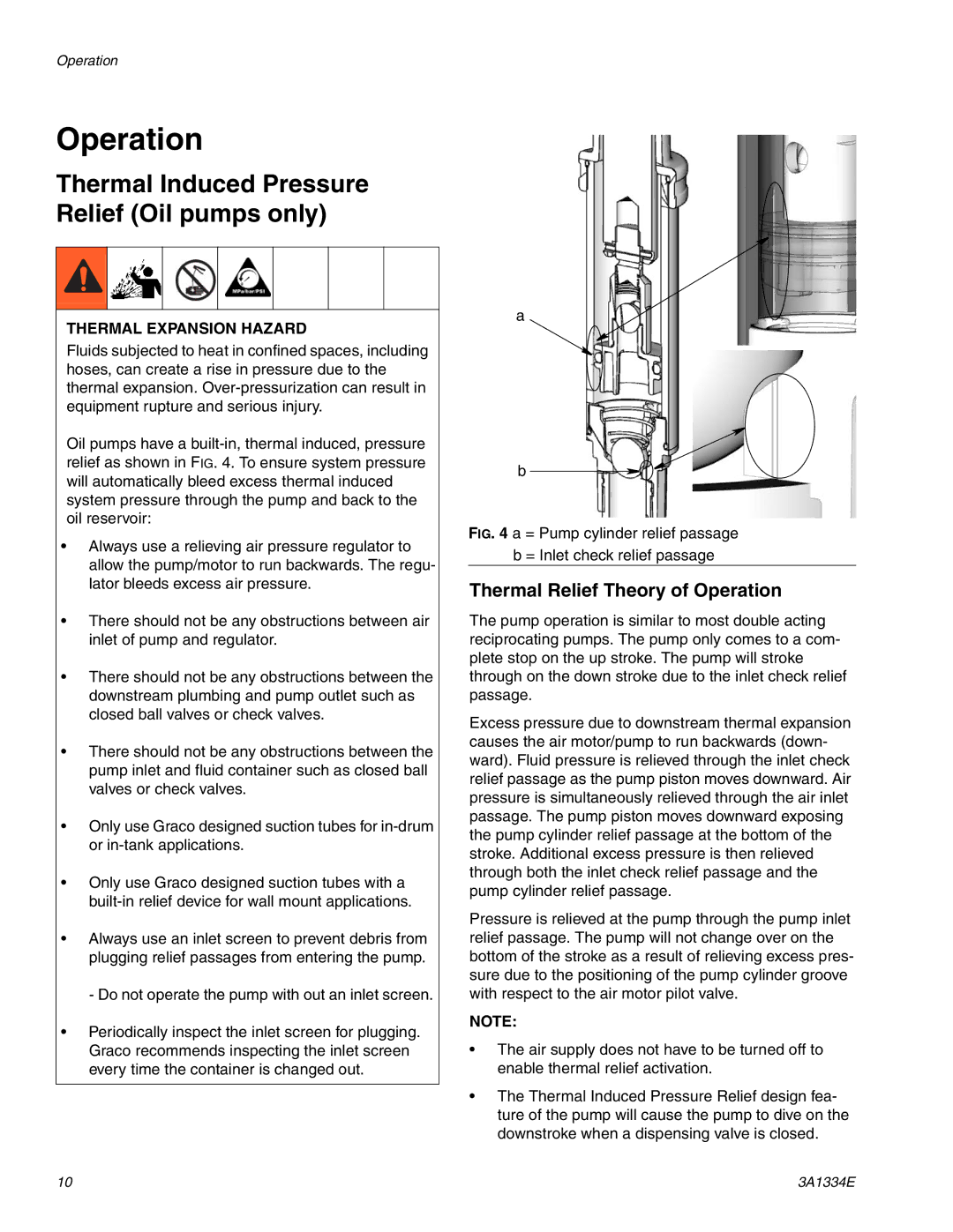
FIG. 4 a = Pump cylinder relief passage b = Inlet check relief passage
Thermal Relief Theory of Operation
The pump operation is similar to most double acting reciprocating pumps. The pump only comes to a com- plete stop on the up stroke. The pump will stroke through on the down stroke due to the inlet check relief passage.
Excess pressure due to downstream thermal expansion causes the air motor/pump to run backwards (down- ward). Fluid pressure is relieved through the inlet check relief passage as the pump piston moves downward. Air pressure is simultaneously relieved through the air inlet passage. The pump piston moves downward exposing the pump cylinder relief passage at the bottom of the stroke. Additional excess pressure is then relieved through both the inlet check relief passage and the pump cylinder relief passage.
Pressure is relieved at the pump through the pump inlet relief passage. The pump will not change over on the bottom of the stroke as a result of relieving excess pres- sure due to the positioning of the pump cylinder groove with respect to the air motor pilot valve.
NOTE:
•The air supply does not have to be turned off to enable thermal relief activation.
•The Thermal Induced Pressure Relief design fea- ture of the pump will cause the pump to dive on the downstroke when a dispensing valve is closed.
10 | 3A1334E |