Operation
Operating the Spray Gun (continued)
1.Follow the Operating Checklist on page 11.
2.To adjust the air cap for a vertical or horizontal spray pattern, first make sure the pressure is relieved. Then loosen the air cap retaining nut, and rotate the air cap as directed in Fig. 5. Tighten the retaining nut until the air cap is held firmly in place; you should not be able to rotate the air cap horns by hand.
Vertical Pattern
Horizontal Pattern
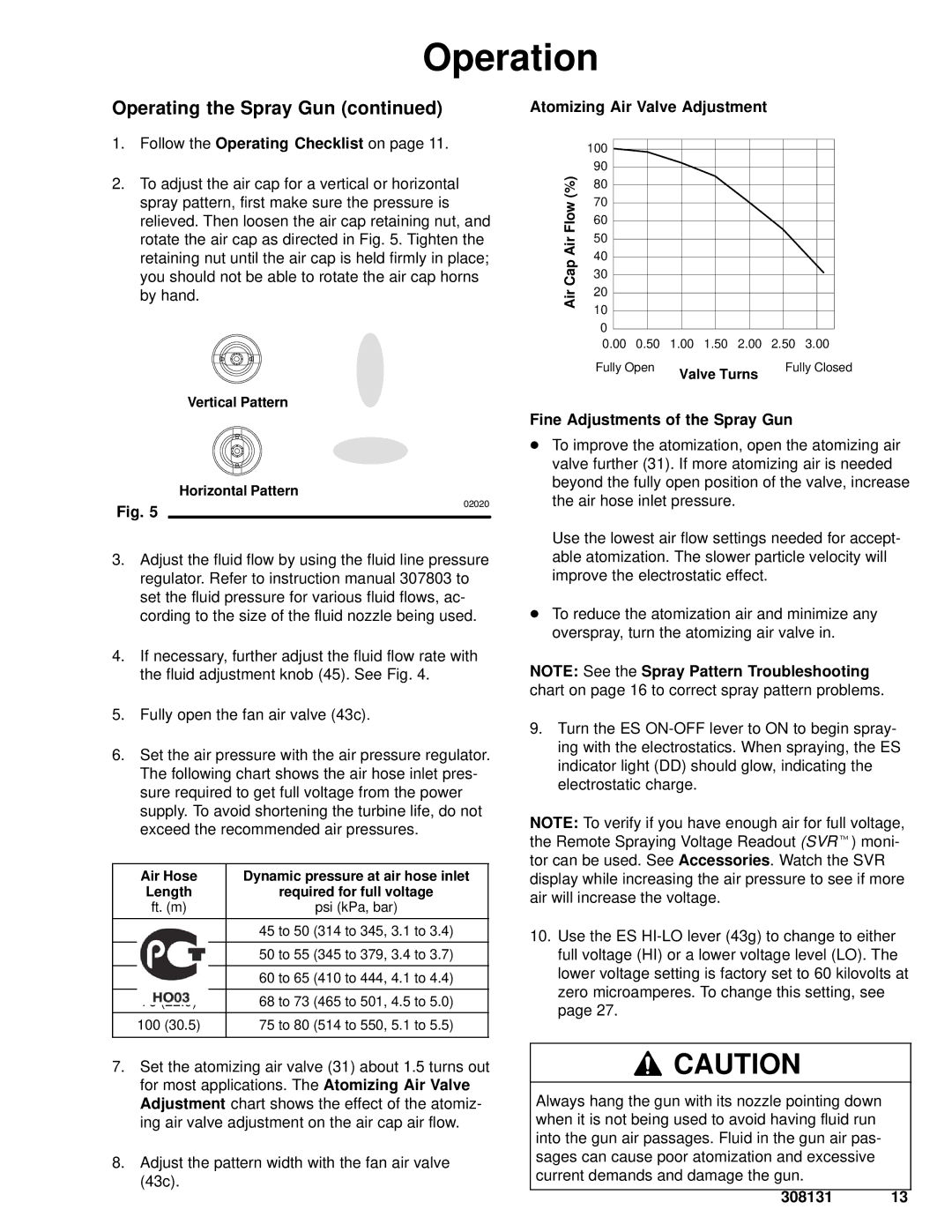
Atomizing Air Valve Adjustment
| 100 |
|
|
|
|
|
|
| 90 |
|
|
|
|
|
|
(%) | 80 |
|
|
|
|
|
|
70 |
|
|
|
|
|
| |
Flow |
|
|
|
|
|
| |
60 |
|
|
|
|
|
| |
50 |
|
|
|
|
|
| |
Air |
|
|
|
|
|
| |
40 |
|
|
|
|
|
| |
Cap |
|
|
|
|
|
| |
30 |
|
|
|
|
|
| |
20 |
|
|
|
|
|
| |
Air |
|
|
|
|
|
| |
10 |
|
|
|
|
|
| |
|
|
|
|
|
|
| |
| 0 |
|
|
|
|
|
|
| 0.00 | 0.50 | 1.00 | 1.50 | 2.00 | 2.50 | 3.00 |
Fully Open | Valve Turns | Fully Closed |
|
|
Fine Adjustments of the Spray Gun
D To improve the atomization, open the atomizing air |
valve further (31). If more atomizing air is needed |
beyond the fully open position of the valve, increase |
Fig. 5
02020
the air hose inlet pressure. |
Use the lowest air flow settings needed for accept- |
3.Adjust the fluid flow by using the fluid line pressure regulator. Refer to instruction manual 307803 to set the fluid pressure for various fluid flows, ac- cording to the size of the fluid nozzle being used.
4.If necessary, further adjust the fluid flow rate with the fluid adjustment knob (45). See Fig. 4.
5.Fully open the fan air valve (43c).
6.Set the air pressure with the air pressure regulator. The following chart shows the air hose inlet pres- sure required to get full voltage from the power supply. To avoid shortening the turbine life, do not exceed the recommended air pressures.
Air Hose | Dynamic pressure at air hose inlet | |
Length | required for full voltage | |
ft. (m) | psi (kPa, bar) | |
|
|
|
15 | (4.6) | 45 to 50 (314 to 345, 3.1 to 3.4) |
|
|
|
25 | (7.6) | 50 to 55 (345 to 379, 3.4 to 3.7) |
|
| |
50 (15.3) | 60 to 65 (410 to 444, 4.1 to 4.4) | |
|
| |
75 (22.9) | 68 to 73 (465 to 501, 4.5 to 5.0) | |
|
|
|
100 | (30.5) | 75 to 80 (514 to 550, 5.1 to 5.5) |
|
|
|
able atomization. The slower particle velocity will |
improve the electrostatic effect. |
D To reduce the atomization air and minimize any |
overspray, turn the atomizing air valve in. |
NOTE: See the Spray Pattern Troubleshooting chart on page 16 to correct spray pattern problems.
9.Turn the ES
NOTE: To verify if you have enough air for full voltage, the Remote Spraying Voltage Readout (SVRt) moni- tor can be used. See Accessories. Watch the SVR display while increasing the air pressure to see if more air will increase the voltage.
10.Use the ES
7.Set the atomizing air valve (31) about 1.5 turns out for most applications. The Atomizing Air Valve Adjustment chart shows the effect of the atomiz- ing air valve adjustment on the air cap air flow.
8.Adjust the pattern width with the fan air valve (43c).
![]() CAUTION
CAUTION
Always hang the gun with its nozzle pointing down when it is not being used to avoid having fluid run into the gun air passages. Fluid in the gun air pas- sages can cause poor atomization and excessive current demands and damage the gun.