Graco Inc 308639L important safety instructions Reassembly

Models: 308639L

1 30
Download 30 pages 44.24 Kb
Page 13
Image 13

Service

Reassembly

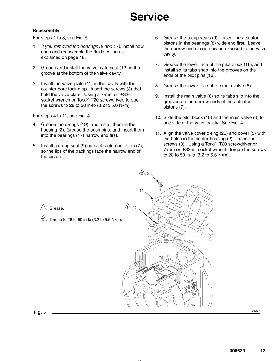
For steps 1 to 3, see Fig. 5.

1.If you removed the bearings (8 and 17), install new ones and reassemble the fluid section as explained on page 18.

2.Grease and install the valve plate seal (12) in the groove at the bottom of the valve cavity.

3.Install the valve plate (11) in the cavity with the counter-bore facing up. Insert the screws (3) that hold the valve plate. Using a 7-mm or 9/32-in. socket wrench or TorxR T20 screwdriver, torque the screws to 28 to 50 in-lb (3.2 to 5.6 NSm).

For steps 4 to 11, see Fig. 4.

4.Grease the o-rings (19), and install them in the housing (2). Grease the push pins, and insert them into the bearings (17) narrow end first.

5.Install a u-cup seal (9) on each actuator piston (7), so the lips of the packings face the narrow end of the piston.

6.Grease the u-cup seals (9). Insert the actuator pistons in the bearings (8) wide end first. Leave the narrow end of each piston exposed in the valve cavity.

7.Grease the lower face of the pilot block (16), and install so its tabs snap into the grooves on the ends of the pilot pins (16).

8.Grease the lower face of the main valve (6).

9.Install the main valve (6) so its tabs slip into the grooves on the narrow ends of the actuator pistons (7).

10.Slide the pilot block (16) and the main valve (6) to one side of the valve cavity. See Fig. 4.

11.Align the valve cover o-ring (20) and cover (5) with the holes in the center housing (2). Insert the screws (3). Using a TorxR T20 screwdriver or

7 mm or 9/32-in. socket wrench, torque the screws to 28 to 50 in-lb (3.2 to 5.6 NSm).

23

11

1 Grease.

1 12

2 Torque to 28 to 50 in-lb (3.2 to 5.6 NSm).

Fig. 5

06324


308639 13

Page 13
Image 13
Graco Inc 308639L important safety instructions Reassembly