PUMP SERVICE

c


. .


WARNING

To reduce the riskof serious bodily injury. including fluid injection. splashing in the eyes or onthe skin, or

.injury frommoving parts, always follow the Pressure Relief Procedure Warning on page 7 before

proceeding.

~~

NOTE: The following metric wrenchesare needed: M6, M10, M30 Allenwrenches.

A pump repair.tool kit, P/N 800-271, is available, It includes packing, extraction and insenion tools.

Repair kits are available. Referto theindividual repairsections, andthepans pagefor moredetails. For the best results, use all the parts in the kit.

Valves

NOTE:

To replacevalves, orderkit part no. 801- 472.

1.Remove the hex plug (205)from the manifold

(206)usingan M30 wrench.

2.Examine the O-ring (204) under the plug and replace it if it is cutor distorted,

3.Removethe valve assembly(203)fromthecavity; the assembly may come apart.

4.Install anew valve (203). Install the O-ring (204) and plug (205) and torque to 75 ft-lb(10.3 Nm).

NOTE:

Retorque the plug after 5 hours of operation.

Pumping Section

1.Remove the six Allen head capscrews (20l)and lockwasher(202)fromthe manifold(206)usinga M6 Allenwrench.

2.Carefully separate the manifold from the crankcase. Itmay be necessryto tapthemanifold lightly with a rubber mallet.

. .

2.Carefully pull the packing retainer (212)fromthe manifold. Examinethe O-ring (213)andreplaceit if it is cut or damaged.

3.Remove the v-packing (210) and head ring (209). Pull out the intermediate retainer ring (211). Remove the v-packing (210) and head ring (209).

4.Inspect all pansand replace as necessary.

5.Thoroughly clean the packing cavities and examine.

6.Lightly grease the packing cavities and then replace the packingsinthe following order: head ring (209). v-packing (210). intermediate ring (211). head ring (209),packing(210). andpacking retainer (212). with the O-ring (213)installedinto the retainer groove.

order and facing the correct direction. See Figure 4. Improperly installed panswill cause a malfunction.

7.Reassemblethe manifoldas instructedinSteps 7 and 8 of Servicing The Plungers.

Servicing The Plungers

the manifoldproperly aligned with the ceramic

NOTE:


Plunger repair kit, pan no. 801-474, is


plungers when removing it.

available to service all the plungers.


3. Carefully examine each plunger (219) and

1. Loosenthe plunger retaining screws (215). 5 to 6


replace it if there is any scoring.

turns, using an M10 wrench. Push the plunger


Servicing The V-Packings

(219) toward the crankcase to separate the


plunger and retaining screw.


NOTE:

2. Remove the screw (215) from'the plunger and


To replace just the v-packings, use kit

examine the O-ring (217). backupring (218)

and

pan no. 801 -662 which willservicethe

copper bearing/gasket washer (216). Replace


entire pump.

these pans, if necessary, using kit partno. 801-


To replace the v-packings. rings and

474.


3. Removethe plunger (219) andflinger (220)from

retainers, order two of kit pan no. 801-

664 toservice the entirepump.

the plunger shaft. Clean, examine and replace


1. If the manifold is not already removed, follow

parts as necessary.


Steps 1 and 2 of pumpingsection.


802-776

9


,

., .

...... ...,,.

Page 9
Image 9
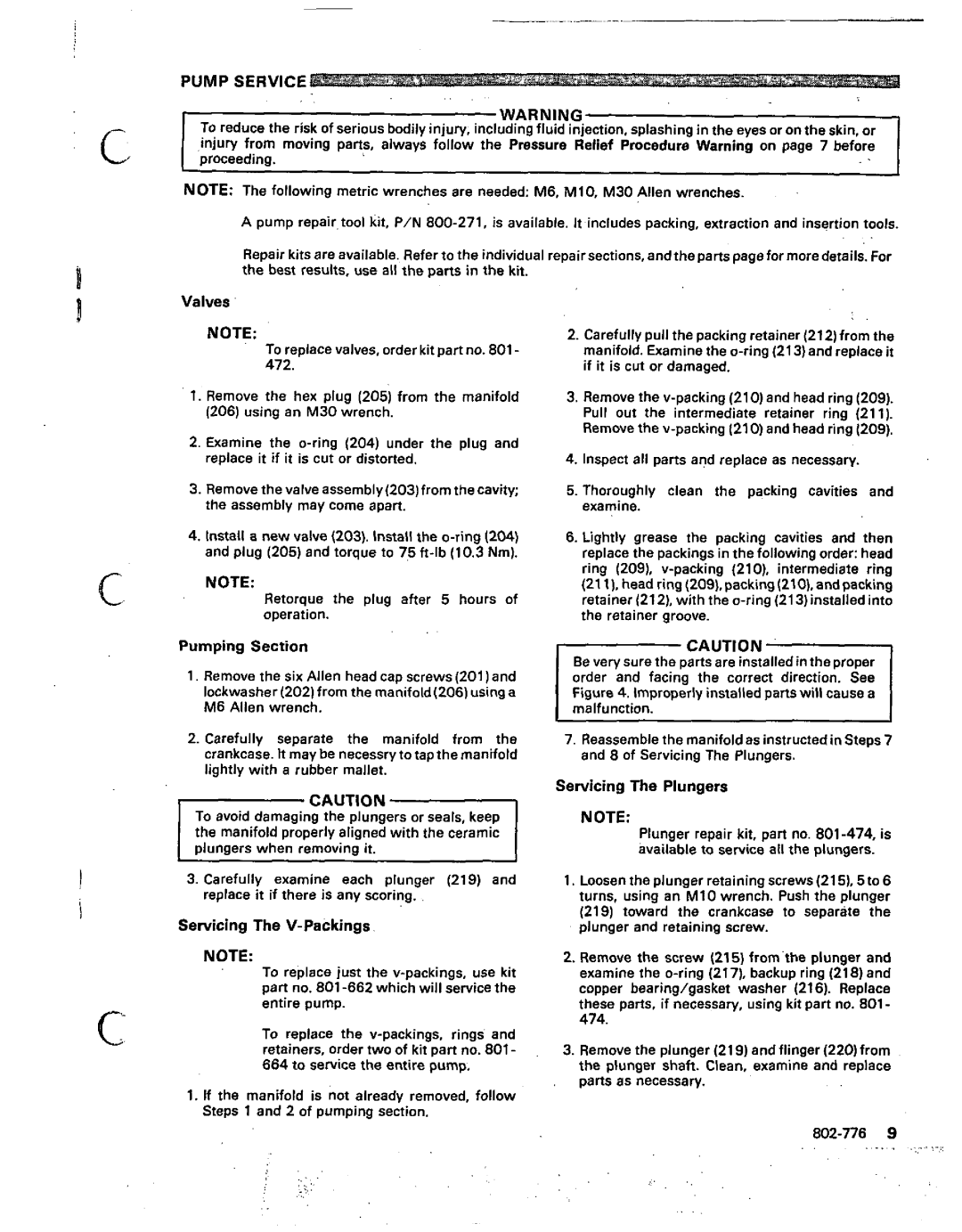
Graco Inc 802-776, 800-232 manual Pump Service, Servicing The V-Packings

800-232, 802-776 specifications

Graco Inc. is a well-known manufacturer in the fluid handling industry, providing a diverse range of products designed to facilitate the efficient and safe transfer of fluids. Among its notable offerings are the Graco Inc. models 802-776 and 800-232, which cater to different applications requiring precision and reliability in fluid handling.

The Graco 802-776 is particularly recognized for its robust design and outstanding performance in high-pressure environments. This model is typically utilized in applications such as air-powered spray guns and paint distribution systems, making it ideal for professionals in the automotive, manufacturing, and construction industries. One of the main features of the 802-776 is its high flow rate, allowing users to complete tasks more efficiently. Additionally, the unit is equipped with a heavy-duty construction that minimizes wear and tear, thus extending its operational lifespan.

On the other hand, the Graco 800-232 is engineered for versatility, providing solutions for a variety of fluid types, including paints, coatings, and adhesives. This unit is highly adaptable, making it suitable for both industrial and commercial uses. A standout feature of the 800-232 is its compact design, which facilitates easy transport and maneuverability in tight spaces. Users appreciate its user-friendly interface, which simplifies operation, reducing the learning curve for new staff or operators.

Both models are equipped with advanced technologies that enhance functionality and safety. For instance, they include pressure control features that provide stability in fluid delivery, ensuring that users can achieve consistent results regardless of application conditions. Furthermore, Graco products are designed with durable materials, ensuring longevity and reliability over time, which is essential in demanding work environments.

Safety is also a critical aspect of the design for both models. They incorporate various safety features to minimize risks during operation, including automatic shut-off mechanisms and pressure relief valves. These technologies not only protect the equipment but also ensure the safety of the personnel operating them.

In summary, Graco Inc. models 802-776 and 800-232 are exemplary products that showcase the company's commitment to delivering high-quality fluid handling solutions. With their unique features, advanced technologies, and user-centric designs, these units are well-suited for a broad range of applications, addressing the demands of modern industries effectively.