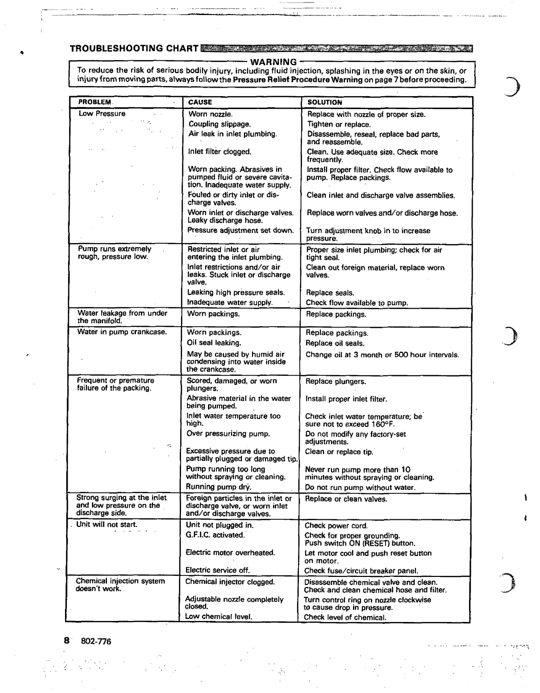
TROUBLESHOOTING CHART

WARNING

To reduce the riskof serious bodily injury, including fluid injection, splashing in the eyes oron the skin, or injUryfrOmmOVingparts, alwaysfollowthe Pressure Relief Procedurewarning onpage7beforeproceeding.

31

PROBLEM

CAUSE

Low Pressure

Worn nozzle.

. :

Coupling slippage.


Air leak in inlet plumbing.

, .

Inlet filterclogged.


Worn packing. Abrasivesin


pumped fluid or severe cavita-


tion. Inadequate water supply.


Fouled ordirty inlet or dis-


charge valves.


Worn inletor discharge valves.


Leaky discharge hose.


Pressure adjustmentset down.

Pump runs extremely

Restricted inlet or air

rough, pressure low.

entering the inlet plumbing.


Inlet restrictions and/or air


leaks. Stuck inlet or discharge


valve.


Leaking high pressure seals.


Inadequate water supply.

Water leakagefrom under

Worn packings.

the manifold.


Water in pump crankcase.

Worn packings.


Oil seal leaking.


May be caused byhumid air


condensing into water inside


the crankcase.

Frequent or premature

Scored, damaged, orworn

failure of the packing.

plungers.


Abrasive material in the water


being pumped.


Inlet water temperature too


nigh.


Over pressurizingpump.

lighten or replace.

Disassemble. reseal, replace bad parts, and reassemble.

Clean. Use adequate size. Check more frequently.

Install proper filter. Check flow available to pump. Replace packings.

Clean inlet and discharge valve assemblies.

Replaceworn valves and/or discharge hose.

Turn adjustment knobin to increase pressure.

Proper sizeinlet plumbing; check for air tight seal.

Cleanout foreign material, replace worn valves.

Replace seals

Check flow available to pump.

Replace packings.

Replace packings. Replace oil seals.

Change oil at 3 month or 500 hour intervals.

Replace plungers.

Install proper inlet filter.

Check inlet water temperature; be sure not toexceed 160°F.

Do not modify any factory-set adjustments.

.3

Strong surging atthe inlet and low pressure on the discharge side.

Unit will not. .start. . .. .

Chemical injection system doesn't work.

3cessive pressure dueto ~artiallyplugged or damagedtip lump running toolong Nithout spraying or cleaning. qunning pump dr$

Foreignparticles in the inletor jischarge valve, orworn inlet tnd/or discharoe valves

Jnit notplugged in. 2.F.I.C. activated.'

ilenric motor overheated

ilectric sewiceoff. :hemica1 injector clogged.

Wjunable nozzle completely :losed.

.ow chemical level.

Clean or replacetip.

Never run pump morethan 10 minutes without spraying or cleaning. Do not run pump without water.

Replace or clean valves.

Check power cord.

Check for proper grounding. Push SwitchON (RESETIbutton.

St motor cool and push reset button ,n motor.

:heck fusehircuit breaker panel.

Jisassemble chemical valve and clean. ;heck and clean chemical hose and filter. [urn control ringon nozzle clockwise

o cause dropin pressure. :heck level of chemical.

8'

802-776


. .

. . .

. . .

. . . .

;

. . , .

....

Page 8
Image 8
Graco Inc 800-232, 802-776 manual Troubleshooting Chart

800-232, 802-776 specifications

Graco Inc. is a well-known manufacturer in the fluid handling industry, providing a diverse range of products designed to facilitate the efficient and safe transfer of fluids. Among its notable offerings are the Graco Inc. models 802-776 and 800-232, which cater to different applications requiring precision and reliability in fluid handling.

The Graco 802-776 is particularly recognized for its robust design and outstanding performance in high-pressure environments. This model is typically utilized in applications such as air-powered spray guns and paint distribution systems, making it ideal for professionals in the automotive, manufacturing, and construction industries. One of the main features of the 802-776 is its high flow rate, allowing users to complete tasks more efficiently. Additionally, the unit is equipped with a heavy-duty construction that minimizes wear and tear, thus extending its operational lifespan.

On the other hand, the Graco 800-232 is engineered for versatility, providing solutions for a variety of fluid types, including paints, coatings, and adhesives. This unit is highly adaptable, making it suitable for both industrial and commercial uses. A standout feature of the 800-232 is its compact design, which facilitates easy transport and maneuverability in tight spaces. Users appreciate its user-friendly interface, which simplifies operation, reducing the learning curve for new staff or operators.

Both models are equipped with advanced technologies that enhance functionality and safety. For instance, they include pressure control features that provide stability in fluid delivery, ensuring that users can achieve consistent results regardless of application conditions. Furthermore, Graco products are designed with durable materials, ensuring longevity and reliability over time, which is essential in demanding work environments.

Safety is also a critical aspect of the design for both models. They incorporate various safety features to minimize risks during operation, including automatic shut-off mechanisms and pressure relief valves. These technologies not only protect the equipment but also ensure the safety of the personnel operating them.

In summary, Graco Inc. models 802-776 and 800-232 are exemplary products that showcase the company's commitment to delivering high-quality fluid handling solutions. With their unique features, advanced technologies, and user-centric designs, these units are well-suited for a broad range of applications, addressing the demands of modern industries effectively.