REPAIR
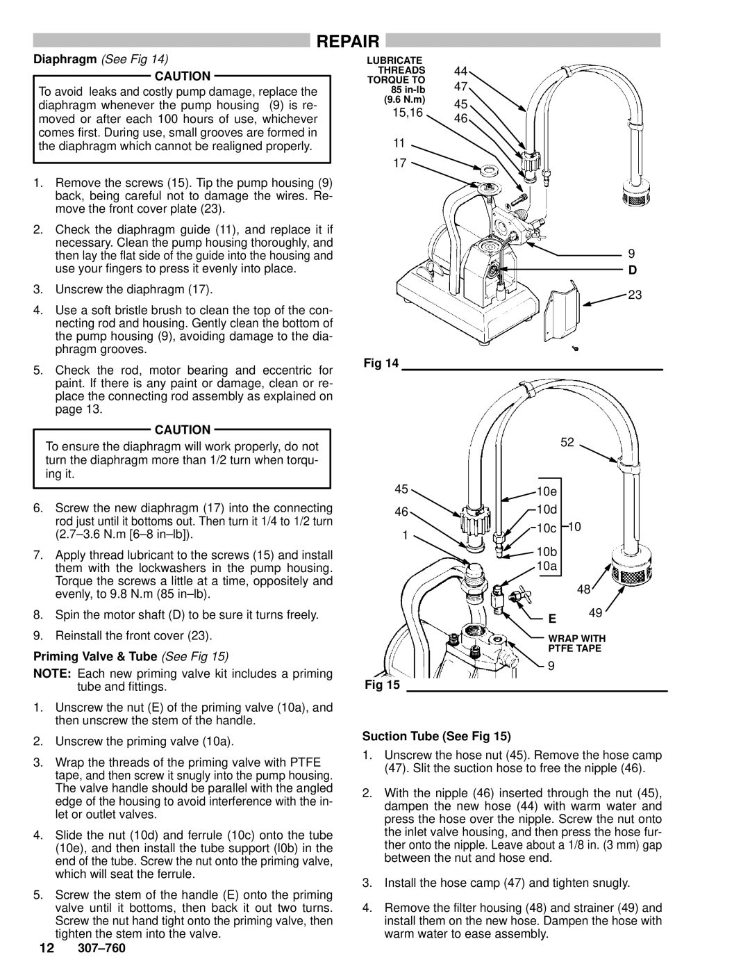
Diaphragm (See Fig 14)
CAUTION
To avoid leaks and costly pump damage, replace the diaphragm whenever the pump housing (9) is re- moved or after each 100 hours of use, whichever comes first. During use, small grooves are formed in the diaphragm which cannot be realigned properly.
1.Remove the screws (15). Tip the pump housing (9) back, being careful not to damage the wires. Re- move the front cover plate (23).
2.Check the diaphragm guide (11), and replace it if necessary. Clean the pump housing thoroughly, and then lay the flat side of the guide into the housing and use your fingers to press it evenly into place.
3.Unscrew the diaphragm (17).
4.Use a soft bristle brush to clean the top of the con- necting rod and housing. Gently clean the bottom of the pump housing (9), avoiding damage to the dia- phragm grooves.
5.Check the rod, motor bearing and eccentric for paint. If there is any paint or damage, clean or re- place the connecting rod assembly as explained on page 13.
CAUTION
To ensure the diaphragm will work properly, do not turn the diaphragm more than 1/2 turn when torqu- ing it.
6. Screw the new diaphragm (17) into the connecting |
rod just until it bottoms out. Then turn it 1/4 to 1/2 turn |
LUBRICATE
THREADS 44
TORQUE TO
85
(9.6 N.m) 45
15,16 46
11
17 ![]()
9
D
![]() 23
23
Fig 14
52
4510e
4610d
(2.7±3.6 N.m [6±8 in±lb]). |
1
10c 10
7. | Apply thread lubricant to the screws (15) and install |
| them with the lockwashers in the pump housing. |
| Torque the screws a little at a time, oppositely and |
| evenly, to 9.8 N.m (85 in±lb). |
8. | Spin the motor shaft (D) to be sure it turns freely. |
9. | Reinstall the front cover (23). |
Priming Valve & Tube (See Fig 15)
NOTE: Each new priming valve kit includes a priming tube and fittings.
1.Unscrew the nut (E) of the priming valve (10a), and then unscrew the stem of the handle.
2.Unscrew the priming valve (10a).
3.Wrap the threads of the priming valve with PTFE R tape, and then screw it snugly into the pump housing. The valve handle should be parallel with the angled edge of the housing to avoid interference with the in- let or outlet valves.
4.Slide the nut (10d) and ferrule (10c) onto the tube (10e), and then install the tube support (l0b) in the end of the tube. Screw the nut onto the priming valve, which will seat the ferrule.
5.Screw the stem of the handle (E) onto the priming valve until it bottoms, then back it out two turns. Screw the nut hand tight onto the priming valve, then tighten the stem into the valve.
12307±760
![]() 10b 10a
10b 10a
48
E 49
WRAP WITH
PTFE TAPE
9
Fig 15
Suction Tube (See Fig 15)
1.Unscrew the hose nut (45). Remove the hose camp (47). Slit the suction hose to free the nipple (46).
2.With the nipple (46) inserted through the nut (45), dampen the new hose (44) with warm water and press the hose over the nipple. Screw the nut onto the inlet valve housing, and then press the hose fur- ther onto the nipple. Leave about a 1/8 in. (3 mm) gap between the nut and hose end.
3.Install the hose camp (47) and tighten snugly.
4.Remove the filter housing (48) and strainer (49) and install them on the new hose. Dampen the hose with warm water to ease assembly.