| SETUP |
SUCTION TUBE | HAND TIGHTEN NUT |
| |
PRIMING TUBE | TIGHTEN SNUGLY WITH |
INLET VALVE | LIGHT WRENCH |
| |
MOTOR | PRIMING VALVE |
|
ON/OFF
SWITCH
PAINT STRAINER
POWER SUPPLY CORD | 7.6 M (25 FT) HOSE |
Add plug according to |
|
local code |
|
SPRING GUARD
MUST BE AT
THIS END
USE TWO | 460 TO 920 MM (18 TO 36 IN.) | |
WRENCHES | ||
TELESCOPING EXTENSION | ||
TO TIGHTEN | ||
| ||
ROLLER VALVE | LOCKNUT | |
| ||
| HAND TIGHTEN ONLY | |
TRIGGER | 12 MM (1/2 IN.) NAP | |
| ||
USE TWO | ROLLER COVER | |
| ||
WRENCHES |
| |
TO TIGHTEN |
| |
| ROLLER FRAME | |
| Apply PTFERtape | |
| to male threads |
| HAND TIGHTEN ONLY | ||
Fig 2 | to avoid cracking roller cover |
|
|
| |||
|
|
| |
| CAUTION |
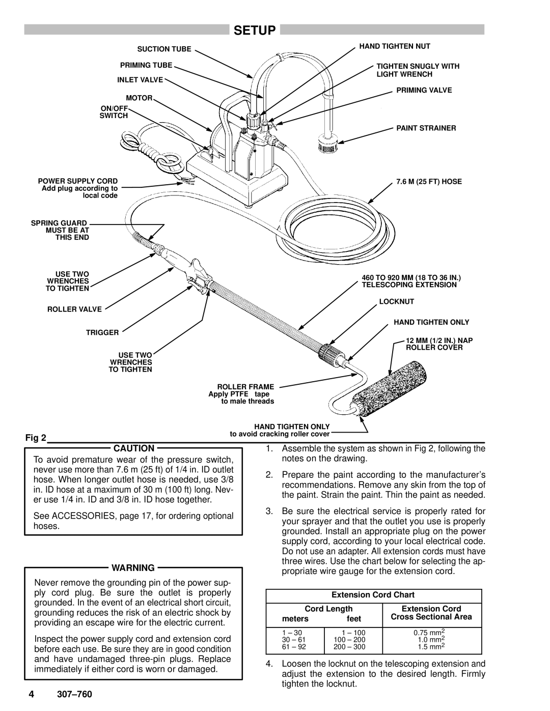
| 1. Assemble the system as shown in Fig 2, following the | ||||
|
| ||||||
To avoid premature wear of the pressure switch, |
|
| notes on the drawing. |
|
| ||
never use more than 7.6 m (25 ft) of 1/4 in. ID outlet |
| 2. Prepare the paint according to the manufacturer's | |||||
hose. When longer outlet hose is needed, use 3/8 |
| ||||||
|
| recommendations. Remove any skin from the top of | |||||
in. ID hose at a maximum of 30 m (100 ft) long. Nev- |
|
| |||||
|
| the paint. Strain the paint. Thin the paint as needed. | |||||
er use 1/4 in. ID and 3/8 in. ID hose together. |
|
| |||||
|
|
|
|
|
| ||
See ACCESSORIES, page 17, for ordering optional |
| 3. Be sure the electrical service is properly rated for | |||||
|
| your sprayer and that the outlet you use is properly | |||||
hoses. |
|
| |||||
|
| grounded. Install an appropriate plug on the power | |||||
|
|
|
| ||||
|
|
|
| supply cord, according to your local electrical code. | |||
|
|
|
| Do not use an adapter. All extension cords must have | |||
| WARNING |
|
| three wires. Use the chart below for selecting the ap- | |||
|
|
| propriate wire gauge for the extension cord. | ||||
|
|
| |||||
|
|
|
| ||||
| Never remove the grounding pin of the power sup- |
|
|
|
|
|
|
| ply cord plug. Be sure the outlet is properly |
|
|
|
|
|
|
|
|
|
| Extension Cord Chart |
| ||
| grounded. In the event of an electrical short circuit, |
|
|
|
|
|
|
|
|
| Cord Length | Extension Cord |
| ||
| grounding reduces the risk of an electric shock by |
|
|
| |||
|
|
| meters | feet | Cross Sectional Area |
| |
| providing an escape wire for the electric current. |
|
|
| |||
|
|
|
|
|
|
| |
| Inspect the power supply cord and extension cord |
|
| 1 ± 30 | 1 ± 100 | 0.75 mm2 |
|
|
|
| 30 ± 61 | 100 ± 200 | 1.0 mm2 |
| |
| before each use. Be sure they are in good condition |
|
| 61 ± 92 | 200 ± 300 | 1.5 mm2 |
|
| and have undamaged |
| 4. Loosen the locknut on the telescoping extension and | ||||
| immediately if either cord is worn or damaged. |
| |||||
|
|
| adjust the extension to the desired length. Firmly | ||||
|
|
|
| ||||
4 | 307±760 |
|
| tighten the locknut. |
|
| |
|
|
|
|
|
| ||