Greenheck Fan 470654 manual Installation of Electrical Wiring

Models: 470654

1 36
Download 36 pages 16.14 Kb
Page 10
Image 10

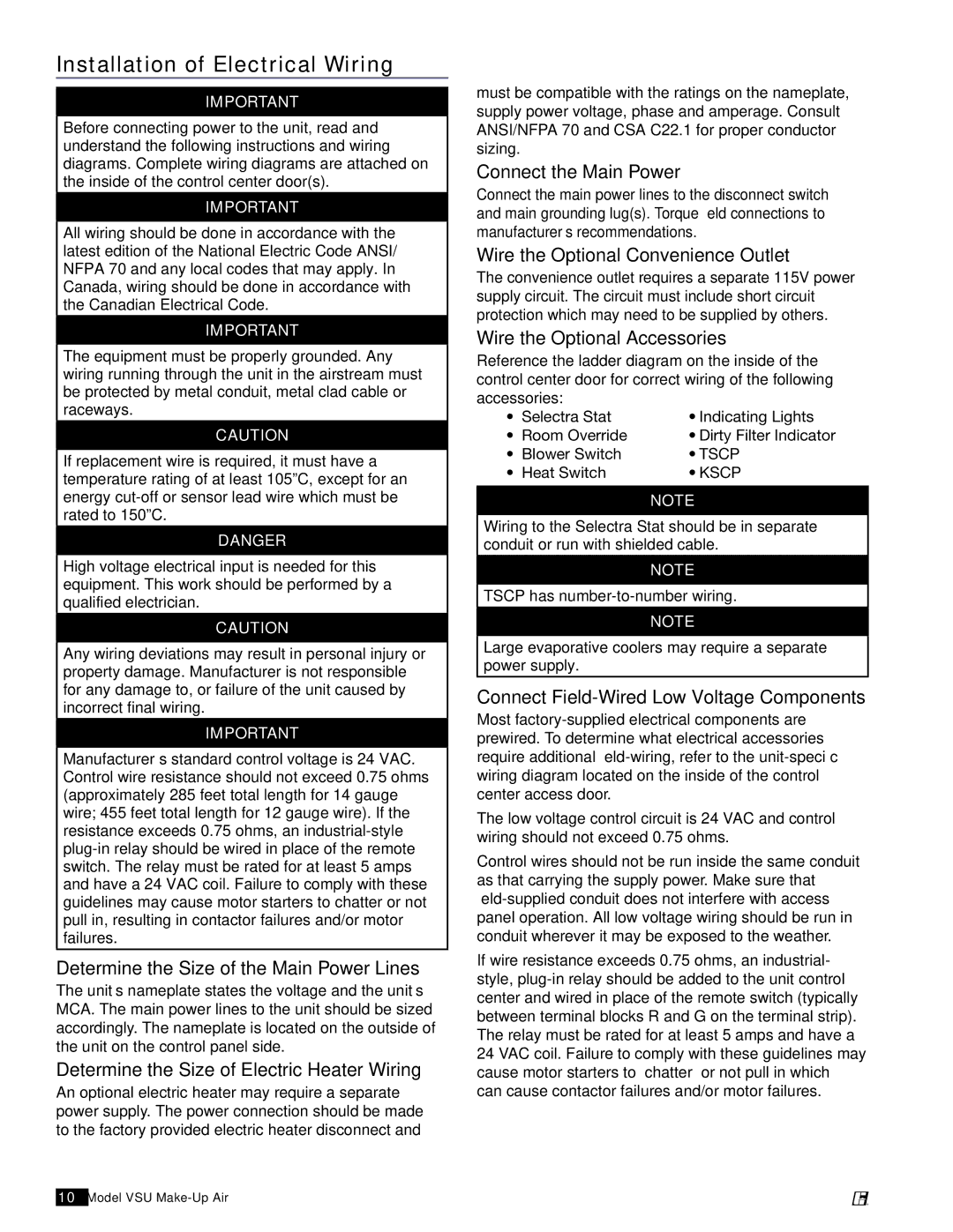
Installation of Electrical Wiring

important

Before connecting power to the unit, read and understand the following instructions and wiring diagrams. Complete wiring diagrams are attached on the inside of the control center door(s).

important

All wiring should be done in accordance with the latest edition of the National Electric Code ANSI/ NFPA 70 and any local codes that may apply. In Canada, wiring should be done in accordance with the Canadian Electrical Code.

important

The equipment must be properly grounded. Any wiring running through the unit in the airstream must be protected by metal conduit, metal clad cable or raceways.

caution

If replacement wire is required, it must have a temperature rating of at least 105ºC, except for an energy cut-off or sensor lead wire which must be rated to 150ºC.

danger

High voltage electrical input is needed for this equipment. This work should be performed by a qualified electrician.

caution

Any wiring deviations may result in personal injury or property damage. Manufacturer is not responsible for any damage to, or failure of the unit caused by incorrect final wiring.

important

Manufacturer’s standard control voltage is 24 VAC. Control wire resistance should not exceed 0.75 ohms (approximately 285 feet total length for 14 gauge wire; 455 feet total length for 12 gauge wire). If the resistance exceeds 0.75 ohms, an industrial-style plug-in relay should be wired in place of the remote switch. The relay must be rated for at least 5 amps and have a 24 VAC coil. Failure to comply with these guidelines may cause motor starters to chatter or not pull in, resulting in contactor failures and/or motor failures.

Determine the Size of the Main Power Lines

The unit’s nameplate states the voltage and the unit’s MCA. The main power lines to the unit should be sized accordingly. The nameplate is located on the outside of the unit on the control panel side.

Determine the Size of Electric Heater Wiring

An optional electric heater may require a separate power supply. The power connection should be made to the factory provided electric heater disconnect and

10Model VSU Make-Up Air

must be compatible with the ratings on the nameplate, supply power voltage, phase and amperage. Consult ANSI/NFPA 70 and CSA C22.1 for proper conductor sizing.

Connect the Main Power

Connect the main power lines to the disconnect switch and main grounding lug(s). Torque field connections to manufacturer’s recommendations.

Wire the Optional Convenience Outlet

The convenience outlet requires a separate 115V power supply circuit. The circuit must include short circuit protection which may need to be supplied by others.

Wire the Optional Accessories

Reference the ladder diagram on the inside of the control center door for correct wiring of the following

accessories:


• Selectra Stat

• Indicating Lights

• Room Override

• Dirty Filter Indicator

• Blower Switch

• TSCP

• Heat Switch

• KSCP


NOTE

Wiring to the Selectra Stat should be in separate conduit or run with shielded cable.

NOTE

TSCP has number-to-number wiring.

NOTE

Large evaporative coolers may require a separate power supply.

Connect Field-Wired Low Voltage Components

Most factory-supplied electrical components are prewired. To determine what electrical accessories require additional field-wiring, refer to the unit-specific wiring diagram located on the inside of the control center access door.

The low voltage control circuit is 24 VAC and control wiring should not exceed 0.75 ohms.

Control wires should not be run inside the same conduit as that carrying the supply power. Make sure that field-supplied conduit does not interfere with access panel operation. All low voltage wiring should be run in conduit wherever it may be exposed to the weather.

If wire resistance exceeds 0.75 ohms, an industrial- style, plug-in relay should be added to the unit control center and wired in place of the remote switch (typically between terminal blocks R and G on the terminal strip). The relay must be rated for at least 5 amps and have a 24 VAC coil. Failure to comply with these guidelines may cause motor starters to “chatter” or not pull in which can cause contactor failures and/or motor failures.

®

Page 10
Image 10
Greenheck Fan 470654 manual Installation of Electrical Wiring

470654 specifications

Greenheck Fan 470654 is a cutting-edge ventilation solution designed to meet the demanding requirements of commercial and industrial applications. Renowned for its reliability and efficiency, this fan model integrates advanced technologies and engineering to provide optimal air movement and control.

One of the standout features of the Greenheck Fan 470654 is its robust construction. Designed with high-quality materials, the fan promotes longevity and durability, making it suitable for use in tough environments. This fan features a heavy-gauge steel housing that minimizes vibration and enhances noise reduction, contributing to a quieter operation, a critical factor in maintaining a serene working environment.

The fan is equipped with a powerful motor that ensures efficient airflow, achieving high performance while consuming minimal energy. This energy efficiency is emphasized through the use of advanced motor technology, including variable frequency drive (VFD) compatibility. VFDs allow for precise control of the fan speed, enabling adjustments based on system demand, thus significantly reducing energy consumption and operating costs.

In terms of airflow performance, the Greenheck Fan 470654 is engineered to provide a high volume of air movement while maintaining static pressure. Its aerodynamic design minimizes resistance, enhancing overall efficiency. The fan is designed to operate across a range of static pressures, making it versatile for different applications, from commercial kitchens to large manufacturing facilities.

Additionally, the fan's installation is straightforward, thanks to its user-centric design. The model incorporates mounting brackets and options for various duct configurations, ensuring seamless integration into existing systems. Maintenance is also made easier with accessible components, allowing technicians to perform regular checks and upkeep without extensive downtime.

Safety features are a priority in the design of the Greenheck Fan 470654. It includes protective features such as thermal overload protection to prevent motor damage and extend operational life. The fan's design also adheres to industry standards and regulations, providing peace of mind for users.

In summary, the Greenheck Fan 470654 is a well-engineered solution that combines durability, efficiency, and advanced technology to deliver superior performance in ventilation applications. With its powerful motor, energy-saving capabilities, and ease of installation and maintenance, it stands out as a reliable choice for professionals seeking optimal airflow management.