INSTALLATION (continued)
WEATHERHOODS
Supply weatherhood will be factory mounted. The exhaust weatherhood is shipped separately as a kit with its own instructions.
EXHAUST DAMPERS
Backdraft dampers for exhaust discharge are mounted in the unit. Motorized dampers are shipped loose (inside ERH) and must be field installed.
ELECTRICAL CONNECTIONS
The electrical supply must be compatible with that shown on the nameplate: voltage, phase, and amperage capacity. The electrical supply line must be properly fused and conform to local and national electrical codes.
All internal electrical components are
Note: Standard factory installed electric post heaters have their own disconnect separate from the unit disconnect. Thus, electric post heaters require a separate power connection.
IMPORTANT: Use minimum 14 ga. wire for 24 volt control power.
Control wire resistance should not exceed 0.75 ohms (approximately 285 feet total length for 14 ga. wire; 455 feet total length for 12 ga. wire). If wire resistance exceeds 0.75 ohms, an
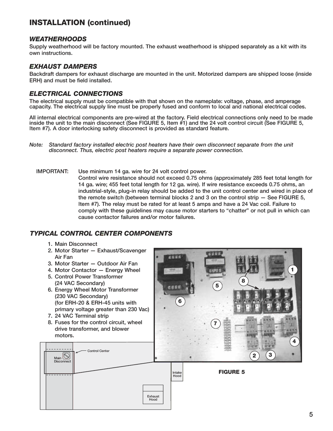
TYPICAL CONTROL CENTER COMPONENTS
1.Main Disconnect
2.Motor Starter — Exhaust/Scavenger Air Fan
3.Motor Starter — Outdoor Air Fan
4. | Motor Contactor — Energy Wheel | 1 | |
5. | Control Power Transformer | 8 | |
| (24 VAC Secondary) | ||
| 5 | ||
6. | Energy Wheel Motor Transformer | ||
| |||
| (230 VAC Secondary) | 6 | |
| (for | ||
| primary voltage greater than 230 Vac) |
| |
7. | 24 VAC Terminal strip |
| |
8. | Fuses for the control circuit, wheel | 7 | |
| drive transformer, and blower |
| |
| motors. |
|
|
| 4 |
Control Center | 2 | 3 |
Off | ||
On |
|
|
Main |
|
|
Disconnect |
|
|
Intake | FIGURE 5 |
|
Hood |
|
|
Exhaust |
|
|
Hood |
|
|
5