FROST CONTROL APPLICATION/OPERATION
When outdoor air temperatures are extremely cold, moisture condensation and frosting on the energy recovery wheel is possible. Frost control is an optional feature that will prevent wheel frosting. Two options are available:
1)Timed Exhaust frost control and
2)Preheat frost control
Timed exhaust frost control includes a thermostat (with
probe) mounted in the supply air inlet compartment (see
Frost Threshold Temp
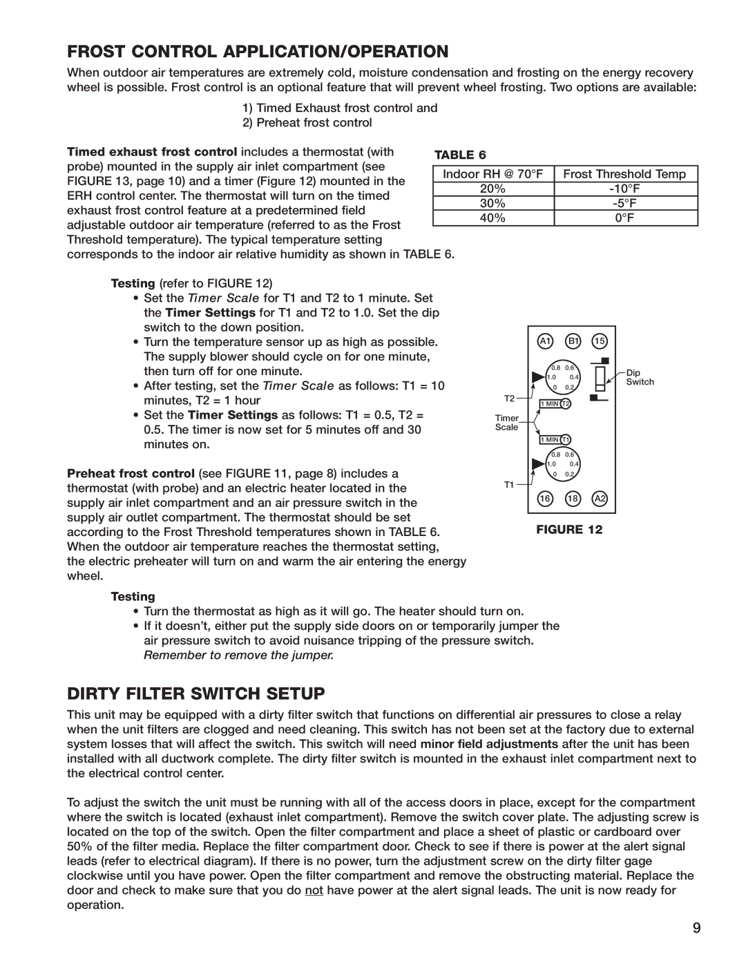
FIGURE 13, page 10) and a timer (Figure 12) mounted in the
-10°F
ERH control center. The thermostat will turn on the timed
exhaust frost control feature at a predetermined field
0°F
adjustable outdoor air temperature (referred to as the Frost Threshold temperature). The typical temperature setting corresponds to the indoor air relative humidity as shown in TABLE 6.
Testing (refer to FIGURE 12)
•Set the Timer Scale for T1 and T2 to 1 minute. Set the Timer Settings for T1 and T2 to 1.0. Set the dip switch to the down position.
• Turn the temperature sensor up as high as possible. |
| A1 | B1 15 |
| ||
The supply blower should cycle on for one minute, |
|
|
|
|
|
|
|
|
|
|
|
| |
then turn off for one minute. |
| 0.8 | 0.6 |
|
| Dip |
|
| |||||
| 1.0 | 0.4 |
|
| ||
• After testing, set the Timer Scale as follows: T1 = 10 |
|
|
| Switch | ||
| 0 | 0.2 |
|
| ||
|
|
|
| |||
minutes, T2 = 1 hour | T2 | 1 MIN T2 |
|
|
| |
|
|
| ||||
|
|
| ||||
• Set the Timer Settings as follows: T1 = 0.5, T2 = | Timer |
|
|
|
|
|
0.5. The timer is now set for 5 minutes off and 30 | Scale |
|
|
|
|
|
minutes on. |
| 1 MIN | T1 |
| ||
|
|
|
|
|
| |
Preheat frost control (see FIGURE 11, page 8) includes a thermostat (with probe) and an electric heater located in the supply air inlet compartment and an air pressure switch in the supply air outlet compartment. The thermostat should be set according to the Frost Threshold temperatures shown in TABLE 6. When the outdoor air temperature reaches the thermostat setting, the electric preheater will turn on and warm the air entering the energy wheel.
0.8 0.6
![]() 1.0 0.4 0 0.2
1.0 0.4 0 0.2
T1
16 18 A2
FIGURE 12
Testing
•Turn the thermostat as high as it will go. The heater should turn on.
•If it doesn’t, either put the supply side doors on or temporarily jumper the air pressure switch to avoid nuisance tripping of the pressure switch. Remember to remove the jumper.
DIRTY FILTER SWITCH SETUP
This unit may be equipped with a dirty filter switch that functions on differential air pressures to close a relay when the unit filters are clogged and need cleaning. This switch has not been set at the factory due to external system losses that will affect the switch. This switch will need minor field adjustments after the unit has been installed with all ductwork complete. The dirty filter switch is mounted in the exhaust inlet compartment next to the electrical control center.
To adjust the switch the unit must be running with all of the access doors in place, except for the compartment where the switch is located (exhaust inlet compartment). Remove the switch cover plate. The adjusting screw is located on the top of the switch. Open the filter compartment and place a sheet of plastic or cardboard over 50% of the filter media. Replace the filter compartment door. Check to see if there is power at the alert signal leads (refer to electrical diagram). If there is no power, turn the adjustment screw on the dirty filter gage clockwise until you have power. Open the filter compartment and remove the obstructing material. Replace the door and check to make sure that you do not have power at the alert signal leads. The unit is now ready for operation.
9