0.8 0.6
1.0 0.4
0 0.2
1 MIN T2
1 MIN T1
0.8 0.6
1.0 0.4
0 0.2
A1 B1 15

Optional Accessories

Frost Control Application/Operation

Extremely cold outdoor air temperatures can cause moisture condensation and frosting on the energy recovery wheel. Frost control is an optional feature that will prevent/control wheel frosting. Three options are available:

1.Timed Exhaust frost control

2.Electric preheat frost control

3.Modulating wheel frost control

All of these options are provided with a thermostat (with probe) mounted in the outdoor air intake compartment and a pressure sensor to monitor pressure drop across the wheel.

Frost Threshold Temperatures

Indoor RH @ 70°F

Frost Threshold Temp


20%

-10º F


30%

-5º F


40%

0º F


The typical temperature setting corresponds to the indoor air relative humidity as shown in the Frost Threshold Temperatures Table and represents when frost can occur. An increase in pressure drop would indicate that frost is occurring. Both the pressure sensor and the outdoor air temperature sensor must trigger in order to initiate frost control. The two sensors together ensure that frost control is only initiated during a real frost condition. Field wiring of a light (or other alarm) between 6 & C in the control center will notify personnel when unit is in frost control mode (refer to Remote Panel Wiring schematics section for wiring details). The following explains the three options in more detail.

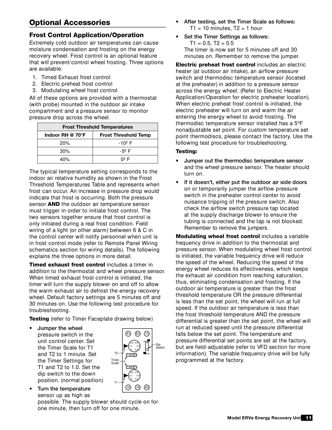
Timed exhaust frost control includes a timer in addition to the thermostat and wheel pressure sensor. When timed exhaust frost control is initiated, the timer will turn the supply blower on and off to allow the warm exhaust air to defrost the energy recovery wheel. Default factory settings are 5 minutes off and 30 minutes on. Use the following test procedure for troubleshooting.

Testing (refer to Timer Faceplate drawing below)

After testing, set the Timer Scale as follows:

T1 = 10 minutes, T2 = 1 hour

Set the Timer Settings as follows:

T1 = 0.5, T2 = 0.5

The timer is now set for 5 minutes off and 30 minutes on. Remember to remove the jumper.

Electric preheat frost control includes an electric heater (at outdoor air intake), an airflow pressure switch and thermodisc temperature sensor (located at the preheater) in addition to a pressure sensor across the energy wheel. (Refer to Electric Heater Application/Operation for electric preheater location). When electric preheat frost control is initiated, the electric preheater will turn on and warm the air entering the energy wheel to avoid frosting. The thermodisc temperature sensor installed has a 5°F nonadjustable set point. For custom temperature set point thermodiscs, please contact the factory. Use the following test procedure for troubleshooting.

Testing:

Jumper out the thermodisc temperature sensor and the wheel pressure sensor. The heater should turn on.

If it doesn’t, either put the outdoor air side doors on or temporarily jumper the airflow pressure switch in the preheater control center to avoid nuisance tripping of the pressure switch. Also check the airflow switch pressure tap located at the supply discharge blower to ensure the tubing is connected and the tap is not blocked. Remember to remove the jumpers.

Modulating wheel frost control includes a variable frequency drive in addition to the thermostat and pressure sensor. When modulating wheel frost control is initiated, the variable frequency drive will reduce the speed of the wheel. Reducing the speed of the energy wheel reduces its effectiveness, which keeps the exhaust air condition from reaching saturation, thus, eliminating condensation and frosting. If the outdoor air temperature is greater than the frost threshold temperature OR the pressure differential

is less than the set point, the wheel will run at full speed. If the outdoor air temperature is less than the frost threshold temperature AND the pressure differential is greater than the set point, the wheel will

Jumper the wheel pressure switch in the unit control center. Set the Timer Scale for T1 and T2 to 1 minute. Set the Timer Settings for

T1 and T2 to 1.0. Set the dip switch to the down position. (normal position)

Dip

Switch

T2

Timer

Scale

T1

run at reduced speed until the pressure differential falls below the set point. The temperature and pressure differential set points are set at the factory, but are field-adjustable (refer to VFD section for more information). The variable frequency drive will be fully programmed at the factory.

• Turn the temperature

16

18

A2

sensor up as high as

possible. The supply blower should cycle on for one minute, then turn off for one minute.

Model ERVe Energy Recovery Unit 11

Page 11
Image 11
Greenheck Fan ERVe manual Optional Accessories, Frost Control Application/Operation

ERVe specifications

The Greenheck Fan ERVe series stands at the forefront of energy-efficient ventilation solutions, specifically designed to meet the growing demands for energy conservation and enhanced indoor air quality in commercial buildings. As part of Greenheck's commitment to innovation, the ERVe series offers a variety of models tailored to diverse applications, including schools, hospitals, and office buildings.

One of the key features of the ERVe series is its advanced energy recovery technology. The ERVe utilizes a heat recovery wheel that efficiently transfers heat and moisture between the exhaust and incoming airstreams. This process significantly reduces heating and cooling loads on HVAC systems, promoting energy savings and improving overall system efficiency. By reclaiming energy that would otherwise be wasted, the ERVe ensures that buildings not only conform to energy codes but also contribute to sustainability goals.

The ERVe series is designed with versatility in mind. It offers multiple configurations, including vertical and horizontal orientations, which makes it adaptable to various installation environments. Additionally, the unit can be equipped with a range of options such as pre-filters, post-filters, and variable speed drive motors, allowing for customization based on specific application needs. This adaptability ensures that the ERVe can meet the specific air quality requirements of different spaces while maintaining optimal airflow.

Another significant characteristic of the ERVe series is its low noise operation. The design incorporates advanced acoustical features, including sound attenuators and insulated panels, which minimize sound transmission and enhance occupant comfort. As noise control becomes increasingly important in settings like educational institutions and healthcare facilities, the ERVe series excels in providing a peaceful indoor environment.

Moreover, the ERVe series is engineered with durability in mind. Constructed from high-quality materials, the units are built to withstand the rigors of continuous operation. The robust design not only extends the service life of the equipment but also reduces maintenance requirements, leading to lower overall operational costs.

In terms of control and monitoring, the ERVe series is compatible with various building management systems, allowing for integration into sophisticated HVAC controls. This feature enables real-time data tracking and optimization, enhancing the efficiency of indoor climate management.

Overall, the Greenheck Fan ERVe series represents a significant advancement in ventilation technology, combining energy efficiency, customizable features, low noise operation, and durability. These characteristics ensure that the ERVe is a reliable choice for modern commercial buildings striving for improved air quality and reduced energy consumption.