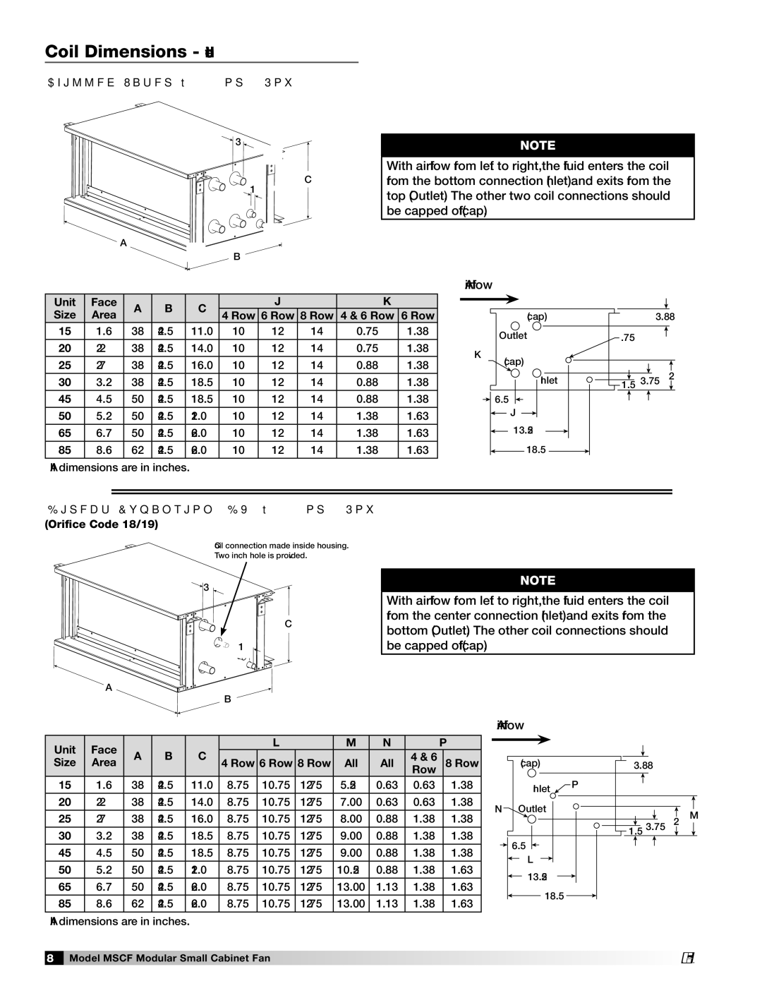
Coil Dimensions - continued
Chilled Water • 4, 6 or 8 Row
![]()
![]() 3
3![]()
C
1
![]() A
A![]()
![]() B
B ![]()
NOTE
With airflow from left to right, the fluid enters the coil from the bottom connection (Inlet) and exits from the top (Outlet). The other two coil connections should be capped off (cap).
Unit | Face | A | B | C |
| J |
|
| K | ||
Size | Area | 4 Row | 6 Row | 8 Row | 4 & 6 Row | 6 Row | |||||
|
|
| |||||||||
15 | 1.6 | 38 | 24.5 | 11.0 | 10 | 12 | 14 | 0.75 |
| 1.38 | |
|
|
|
|
|
|
|
|
|
|
| |
20 | 2.2 | 38 | 24.5 | 14.0 | 10 | 12 | 14 | 0.75 |
| 1.38 | |
|
|
|
|
|
|
|
|
|
|
| |
25 | 2.7 | 38 | 24.5 | 16.0 | 10 | 12 | 14 | 0.88 |
| 1.38 | |
30 | 3.2 | 38 | 24.5 | 18.5 | 10 | 12 | 14 | 0.88 |
| 1.38 | |
|
|
|
|
|
|
|
|
|
|
| |
45 | 4.5 | 50 | 24.5 | 18.5 | 10 | 12 | 14 | 0.88 |
| 1.38 | |
|
|
|
|
|
|
|
|
|
|
| |
50 | 5.2 | 50 | 24.5 | 21.0 | 10 | 12 | 14 | 1.38 |
| 1.63 | |
|
|
|
|
|
|
|
|
|
|
| |
65 | 6.7 | 50 | 24.5 | 26.0 | 10 | 12 | 14 | 1.38 |
| 1.63 | |
|
|
|
|
|
|
|
|
|
|
| |
85 | 8.6 | 62 | 24.5 | 26.0 | 10 | 12 | 14 | 1.38 |
| 1.63 | |
|
|
|
|
|
|
|
|
|
|
| |
All dimensions are in inches.
Airflow |
|
| |
| (cap) | 3.88 | |
| Outlet | .75 |
|
K | (cap) |
|
|
|
|
| |
| Inlet | 1.5 3.75 | 2 |
| 6.5 |
|
|
| J |
|
|
| 13.25 |
|
|
| 18.5 |
|
|
Direct Expansion (DX) • 4, 6 or 8 Row (Orifice Code 18/19)
Coil connection made inside housing.
Two inch hole is provided.
![]()
![]() 3
3
C
1
A![]()
![]()
![]() B
B
NOTE
With airflow from left to right, the fluid enters the coil from the center connection (Inlet) and exits from the bottom (Outlet). The other coil connections should be capped off (cap).
Unit | Face |
|
|
|
| L |
| M | N |
| P | |
A | B | C |
|
|
|
|
| 4 & 6 |
|
| ||
Size | Area | 4 Row | 6 Row | 8 Row | All | All |
| 8 Row | ||||
|
|
|
|
|
|
|
|
|
| Row |
|
|
15 | 1.6 | 38 | 24.5 | 11.0 | 8.75 | 10.75 | 12.75 | 5.25 | 0.63 | 0.63 |
| 1.38 |
|
|
|
|
|
|
|
|
|
|
|
|
|
20 | 2.2 | 38 | 24.5 | 14.0 | 8.75 | 10.75 | 12.75 | 7.00 | 0.63 | 0.63 |
| 1.38 |
|
|
|
|
|
|
|
|
|
|
|
|
|
25 | 2.7 | 38 | 24.5 | 16.0 | 8.75 | 10.75 | 12.75 | 8.00 | 0.88 | 1.38 |
| 1.38 |
30 | 3.2 | 38 | 24.5 | 18.5 | 8.75 | 10.75 | 12.75 | 9.00 | 0.88 | 1.38 |
| 1.38 |
|
|
|
|
|
|
|
|
|
|
|
|
|
45 | 4.5 | 50 | 24.5 | 18.5 | 8.75 | 10.75 | 12.75 | 9.00 | 0.88 | 1.38 |
| 1.38 |
|
|
|
|
|
|
|
|
|
|
|
|
|
50 | 5.2 | 50 | 24.5 | 21.0 | 8.75 | 10.75 | 12.75 | 10.25 | 0.88 | 1.38 |
| 1.63 |
|
|
|
|
|
|
|
|
|
|
|
|
|
65 | 6.7 | 50 | 24.5 | 26.0 | 8.75 | 10.75 | 12.75 | 13.00 | 1.13 | 1.38 |
| 1.63 |
|
|
|
|
|
|
|
|
|
|
|
|
|
85 | 8.6 | 62 | 24.5 | 26.0 | 8.75 | 10.75 | 12.75 | 13.00 | 1.13 | 1.38 |
| 1.63 |
|
|
|
|
|
|
|
|
|
|
|
|
|
All dimensions are in inches.
Airflow
(cap) | 3.88 |
Inlet | P |
| |
N Outlet | 1.5 3.75 2 M |
| |
6.5 |
|
L |
|
13.25 |
|
18.5 |
|
8 Model MSCF Modular Small Cabinet Fan
®
