Table of Contents
Basic Operation |
|
|
| 3 |
Installation |
|
|
|
|
Supplemental Installation, Operation and |
|
|
| |
Maintenance Manuals |
|
|
| 3 |
Installation |
|
|
| 3 |
Installation Stages | . | . | 4 | |
Lifting with a Crane or Forklift |
|
|
| 4 |
Roof Curb and Rail Mounting |
|
|
|
|
Recommended Roof Opening |
|
|
| 4 |
Service Clearances | . | . | 5 | |
Roof Curb Mounting |
|
|
| 6 |
Curb Dimensions and Weights | . | . | 6 | |
Ductwork Connections |
|
|
| 6 |
Rail Mounting / Layout |
|
|
| 7 |
Access Panel Description and Location . | . | . | 7 | |
Dimensional Data |
|
|
| 8 |
Drain Trap . . . . . . . . . . . . . . . 8 | ||||
Electrical Information |
|
|
|
|
General Electrical Information |
|
|
| 9 |
Control Center Components | . | . 10 | ||
Electric Heater Application/Operation . . | . | . 10 | ||
Optional Accessories |
|
|
|
|
Frost Control Application/Operation . . . | . | . 11 | ||
Economizer Application/Operation |
|
|
| 11 |
Variable Frequency Drives and Wiring . . | . | |||
Typical Wiring Diagram | . | . 14 | ||
Sensors and Lights | . | . 15 | ||
Remote Control Panel and Wiring . . . . | . | . 16 | ||
Sensors Mounted by Factory | . | . 17 | ||
Sequence of Operation |
|
|
|
|
|
|
|
| |
General |
|
|
| 18 |
Optional Accessories | . | . 19 | ||
Unit | ||||
Routine Maintenance Checklist |
|
|
|
|
Overview | . | . 22 | ||
General |
|
|
| 23 |
Fan Belts | . | . 23 | ||
Fan Motors | . | . 23 | ||
Fan Wheel and Fasteners |
|
|
| 24 |
Fan Bearings |
|
|
| 24 |
Filters |
|
|
| 24 |
Door Seal Maintenance | . | . 24 | ||
Parts List |
|
|
| 25 |
Sequence of Operation | . | . | 25 | |
Troubleshooting – Airflow | . | . | 26 | |
Troubleshooting – Unit |
|
| ||
Maintenance Log | ||||
Warranty | Backcover | |||
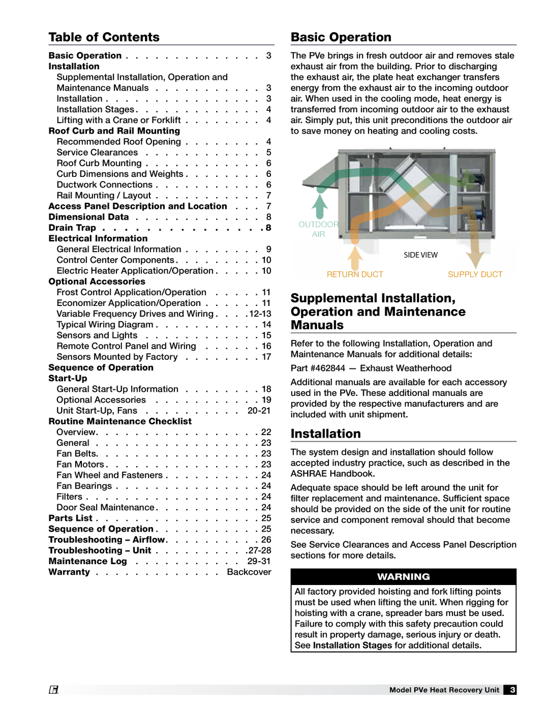
Basic Operation
The PVe brings in fresh outdoor air and removes stale exhaust air from the building. Prior to discharging the exhaust air, the plate heat exchanger transfers energy from the exhaust air to the incoming outdoor air. When used in the cooling mode, heat energy is transferred from incoming outdoor air to the exhaust air. Simply put, this unit preconditions the outdoor air to save money on heating and cooling costs.
OUTDOOR
AIR
SIDE VIEW
RETURN DUCT | SUPPLY DUCT |
Supplemental Installation,
Operation and Maintenance
Manuals
Refer to the following Installation, Operation and Maintenance Manuals for additional details:
Part #462844 — Exhaust Weatherhood
Additional manuals are available for each accessory used in the PVe. These additional manuals are provided by the respective manufacturers and are included with unit shipment.
Installation
The system design and installation should follow accepted industry practice, such as described in the ASHRAE Handbook.
Adequate space should be left around the unit for filter replacement and maintenance. Sufficient space should be provided on the side of the unit for routine service and component removal should that become necessary.
See Service Clearances and Access Panel Description sections for more details.
Warning
All factory provided hoisting and fork lifting points must be used when lifting the unit. When rigging for hoisting with a crane, spreader bars must be used. Failure to comply with this safety precaution could result in property damage, serious injury or death. See Installation Stages for additional details.
Model PVe Heat Recovery Unit 3