Basic Jointer
Controls
All basic controls used during routine jointer oper- ations on the G0634XP are the same as those described on Pages
Table Movement: Unlock the table lock levers, then loosen the cap screws on the infeed handgrip or outfeed table adjustment knob (see Figure 4) before moving the infeed and outfeed tables. Use an adjustable wrench to turn the outfeed adjust- ment knob.
Cap Screw |
| Cap |
|
| Screw |
|
|
|
Outfeed Table |
| Infeed |
Adj. Knob |
| Handgrip |
|
|
|
Figure 4. Table control locations.
Fence Movement: The fence lock lever keeps the fence in position (see Figure 5). To move the fence, loosen the lever, slide the fence in the desired direction, then tighten the lever.
Tilt
Knob
Lock Lever
Figure 5. Fence lock location.
Model G0634XP (Mfg. 4/11+)
Fence Tilting: The tilt knob (Figure 5) secures the fence at any position in the available range. Fence stops set the fence at 90° or 45° outward. The tilt knob must be tightened before jointing. See Page 10 in this insert for more detail on adjusting the fence stops.
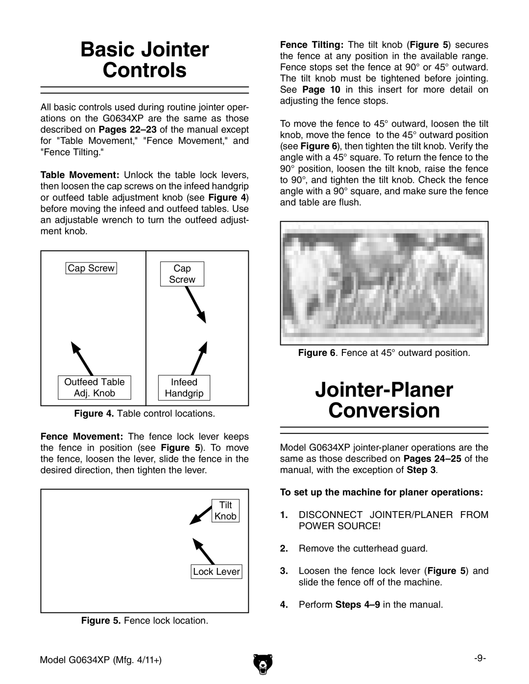
To move the fence to 45° outward, loosen the tilt knob, move the fence to the 45° outward position (see Figure 6), then tighten the tilt knob. Verify the angle with a 45° square. To return the fence to the 90° position, loosen the tilt knob, raise the fence to 90°, and tighten the tilt knob. Check the fence angle with a 90° square, and make sure the fence and table are flush.
Figure 6. Fence at 45° outward position.
Jointer-Planer
Conversion
Model G0634XP
To set up the machine for planer operations:
1.DISCONNECT JOINTER/PLANER FROM POWER SOURCE!
2.Remove the cutterhead guard.
3.Loosen the fence lock lever (Figure 5) and slide the fence off of the machine.
4.Perform Steps