3.Directional changes should be kept to a mini- mum. The more directional change fittings you use directly increases the overall resis- tance to airflow.
4.Gradual directional changes are more effi- cient than sudden directional changes (i.e. use the largest corner radius possible when changing hose or pipe direction).
5.Each individual branch line should have a blast gate immediately after the branch to control suction from one machine to another.
6.The simpler the system, the more efficient and less costly it will be.
Step 4. Determine Required CFM of Each Machine
Since each machine produces a different amount of sawdust, the requirements for the minimum amount of CFM to move that sawdust is unique to the machine (for example, a planer produces more sawdust than a table saw). Knowing this required CFM is important to gauging which size of duct to use.
Figure 20 gives you a close estimation of the airflow your machine requires. Keep in mind that machines that generate the most sawdust should be placed closest to the dust collector. If the machine has multiple dust ports, the total CFM required is the sum of all ports.
If your machine doesn't have a built in dust port, use Figure 21 to determine which size of dust port to install on your machine.
Machine | Average Dust Port Size | |
Table Saw | 4" | |
2" | ||
Jointer (6" and smaller) | 4" | |
Jointer | 5" | |
Thickness Planer (13" and smaller) | 4" | |
Thickness Planer | 6" | |
Shaper | 4" | |
Router (mounted to table) | 2" | |
Bandsaw | 4" | |
Lathe | 4" | |
Disc Sander (12" and smaller) | 2" | |
Disc Sander | 4" | |
Belt Sander (6" and smaller) | 2" | |
Belt Sander | 3" | |
Edge Sander (6" x 80" and smaller) | 4" | |
Edge Sander (6" x 80" and larger) | 5" | |
Drum Sander (24" and smaller) | 2 x 4" | |
Drum Sander (24" and larger) | 4 x 4" | |
Widebelt Sander (18" and smaller) | 5" | |
Widebelt Sander | 2 x 6" | |
Widebelt Sander (24"_51" double head).5 x 4"
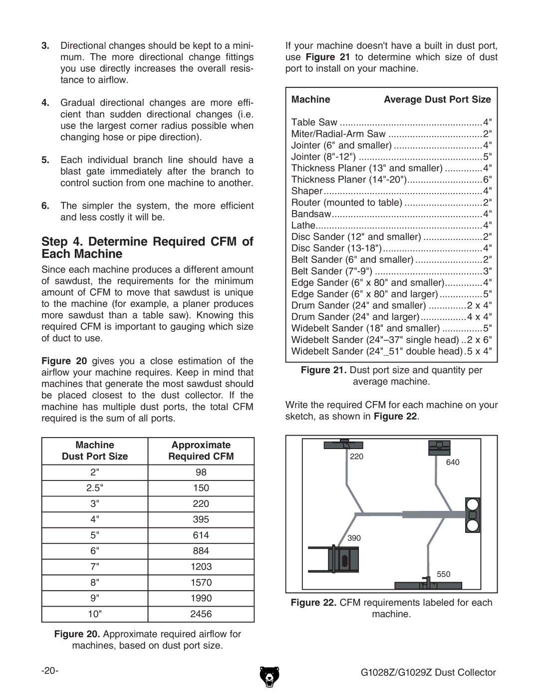
Figure 21. Dust port size and quantity per
average machine.
Write the required CFM for each machine on your sketch, as shown in Figure 22.
Machine | Approximate |
Dust Port Size | Required CFM |
|
|
2" | 98 |
|
|
2.5" | 150 |
|
|
3" | 220 |
|
|
4" | 395 |
|
|
5" | 614 |
|
|
6" | 884 |
���
��
���
��� ���
7" | 1203 |
|
|
8" | 1570 |
|
|
9" | 1990 |
|
|
10" | 2456 |
Figure 20. Approximate required airflow for
machines, based on dust port size.
���
���