Chain Drive
Adjust the chain drive by loosening the chain ten- sioner and loosen the chain until you can turn each corner sprocket independently. If the back of the table is too high, the back two sprockets will need to be rotated clockwise to lower the table. Each tooth on the sprocket represents
.016" of vertical movement as the cogs are turned. Make sure, as you turn the sprocket, to keep an accurate tooth count to ensure that the table is lowered equally on both the left and right sides. Turn the sprockets in small increments until the front clearance matches the back.
When the
.016'' tolerance, tighten the idler sprocket on the chain drive and tighten the lock bolts.
With the
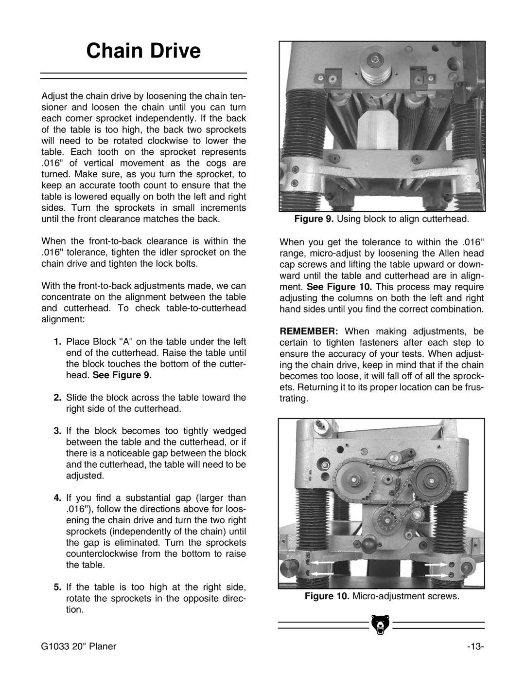
1.Place Block ''A'' on the table under the left end of the cutterhead. Raise the table until the block touches the bottom of the cutter- head. See Figure 9.
2.Slide the block across the table toward the right side of the cutterhead.
3.If the block becomes too tightly wedged between the table and the cutterhead, or if there is a noticeable gap between the block and the cutterhead, the table will need to be adjusted.
4.If you find a substantial gap (larger than
.016''), follow the directions above for loos- ening the chain drive and turn the two right sprockets (independently of the chain) until the gap is eliminated. Turn the sprockets counterclockwise from the bottom to raise the table.
5.If the table is too high at the right side, rotate the sprockets in the opposite direc- tion.
Figure 9. Using block to align cutterhead.
When you get the tolerance to within the .016'' range, micro-adjust by loosening the Allen head cap screws and lifting the table upward or down- ward until the table and cutterhead are in align- ment. See Figure 10. This process may require adjusting the columns on both the left and right hand sides until you find the correct combination.
REMEMBER: When making adjustments, be certain to tighten fasteners after each step to ensure the accuracy of your tests. When adjust- ing the chain drive, keep in mind that if the chain becomes too loose, it will fall off of all the sprock- ets. Returning it to its proper location can be frus- trating.
Figure 10. Micro-adjustment screws.
G1033 20" Planer |