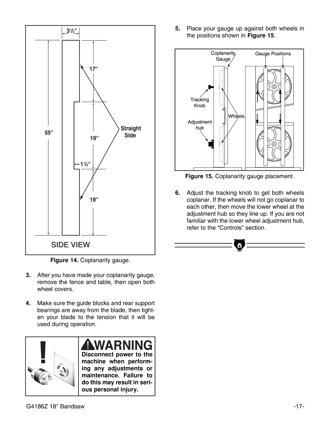
Figure 14. Coplanarity gauge.
3.After you have made your coplanarity gauge, remove the fence and table, then open both wheel covers.
4.Make sure the guide blocks and rear support bearings are away from the blade, then tight- en your blade to the tension that it will be used during operation.
Disconnect power to the machine when perform- ing any adjustments or maintenance. Failure to do this may result in seri- ous personal injury.
5.Place your gauge up against both wheels in the positions shown in Figure 15.
Figure 15. Coplanarity gauge placement.
6.Adjust the tracking knob to get both wheels coplanar. If the wheels will not go coplanar to each other, then move the lower wheel at the adjustment hub so they line up. If you are not familiar with the lower wheel adjustment hub, refer to the ÒControlsÓ section.
G4186Z 18" Bandsaw |
