8.Insert the bridge into the bridge cavity and align the bridge with the guitar center line.
9.Using the long straightedge, measure 251⁄2" from the fretboard side of the nut slot (Figure 13) along the center line to the bridge point (Figure 14), and mark this location on the guitar.
Nut
Slot
11.Align the control plate, pick guard, and bridge so the bridge is parallel to the control plate (leave an even distance between the pickguard and bridge).
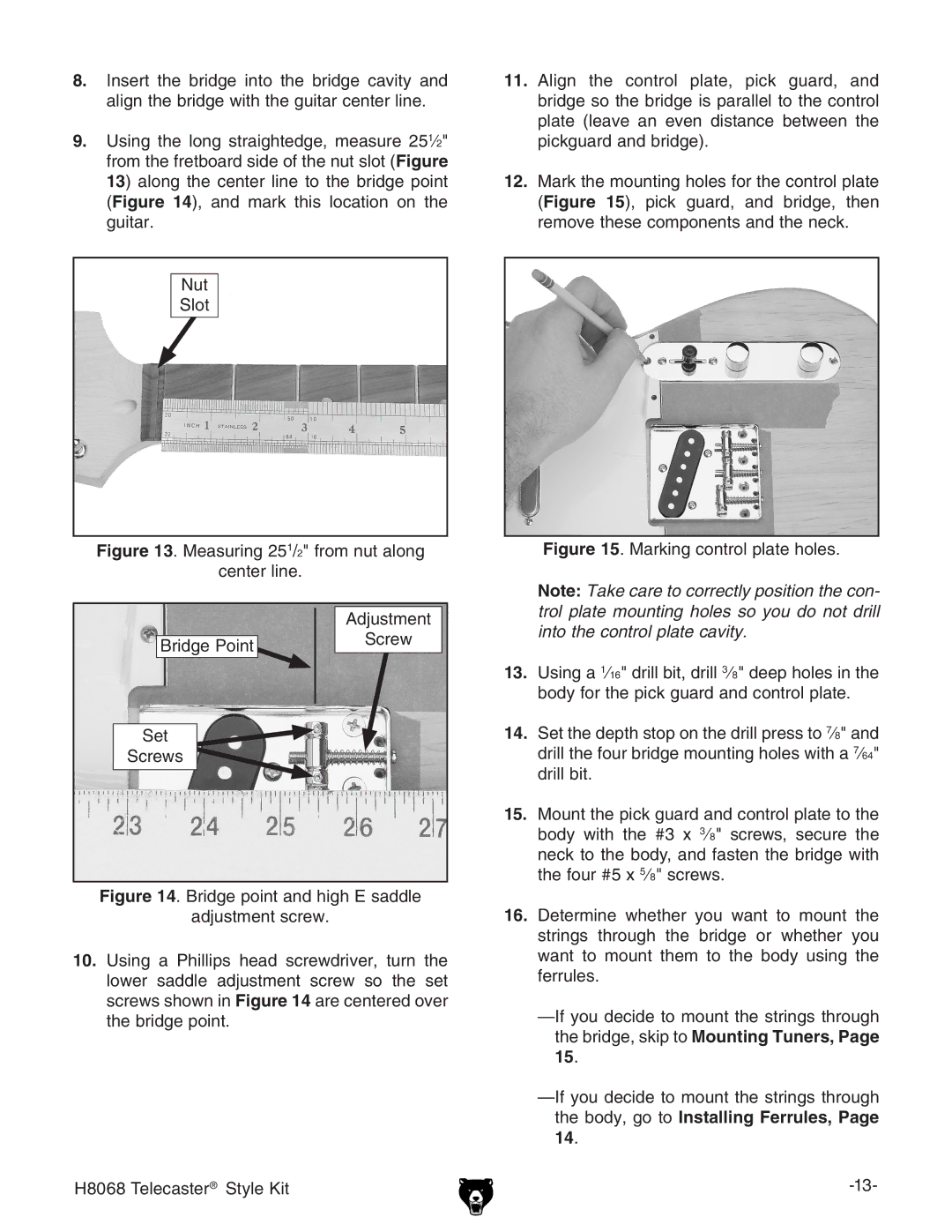
12.Mark the mounting holes for the control plate (Figure 15), pick guard, and bridge, then remove these components and the neck.
Figure 13. Measuring 251/2" from nut along | Figure 15. Marking control plate holes. |
center line. |
|
|
| Note: Take care to correctly position the con- | ||||||||||||
| Adjustment | trol plate mounting holes so you do not drill | ||||||||||||
| into the control plate cavity. |
|
|
|
| |||||||||
Bridge Point | Screw |
|
|
|
| |||||||||
|
|
|
|
|
|
|
|
|
|
|
|
| ||
|
|
|
|
|
|
|
|
|
|
|
|
|
| |
| 13. | Using a | 1 | ⁄16" drill bit, drill | 3 | ⁄8" deep holes in the | ||||||||
|
|
| ||||||||||||
|
| body for the pick guard and control plate. |
|
| ||||||||||
Set | 14. Set the depth stop on the drill press to | 7 | ⁄8" and | |||||||||||
| ||||||||||||||
| drill the four bridge mounting holes with a | 7 | ⁄64" | |||||||||||
Screws |
| |||||||||||||
|
| |||||||||||||
| drill bit. |
|
|
|
|
|
|
|
|
|
|
|
| |
|
|
|
|
|
|
|
|
|
|
|
|
|
| |
| 15. Mount the pick guard and control plate to the | |||||||||||||
|
| body with the #3 x | 3 | ⁄8" |
| screws, secure the | ||||||||
|
|
|
| |||||||||||
|
| neck to the body, and fasten the bridge with | ||||||||||||
|
| the four #5 x | 5 | ⁄8" screws. |
|
|
|
|
| |||||
|
|
|
|
|
|
|
| |||||||
Figure 14. Bridge point and high E saddle
adjustment screw.
10.Using a Phillips head screwdriver, turn the lower saddle adjustment screw so the set screws shown in Figure 14 are centered over the bridge point.
16.Determine whether you want to mount the strings through the bridge or whether you want to mount them to the body using the ferrules.
—If you decide to mount the strings through the bridge, skip to Mounting Tuners, Page 15.
| |
| the body, go to Installing Ferrules, Page |
| 14. |
H8068 Telecaster® Style Kit |