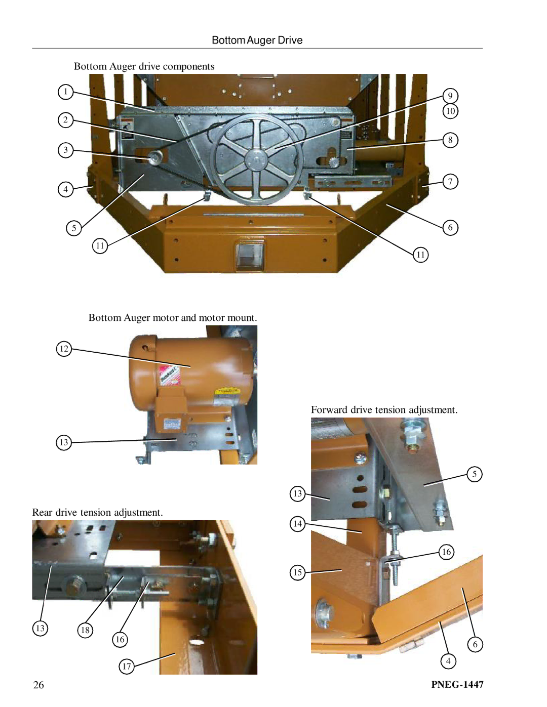
Main
Page
Page
Page
Page
7
Frame Center cross ties.
5
3 44a
Page
Page
10
Meter Rolls and Their Placement in the Dryer
This end is the front (fan/heater) end of the dryer.
Metering Rolls and their placement in the dryer.
11
The part number list above covers all parts pointed out on pages 8, 9, and 10.
Meter Rolls and Their Placement in the Dryer
Page
13
Meter Roll Upper Shield Assembly Close up of of meter roll upper shield assembly.
14
Outside Screens / Meter Roll Access Door
Meter roll access door.
Page
16
Clean Out Doors
Clean out door handle mechanism.
Clean out door hinge.
Front and rear handle mechanisms (rear shown in photo).
17
Clean Out Doors Center handle mechanisms (this handle mechanism stradles the center cross channels).
1a 14
3a
3a 11
18
Front End Panels / Fan Support / grill guards
19
Rear access door (outside).
Rear access door (inside).
Rear End Panels / Rear Access Door
20
Front Ladder Assembly
21
Rear Ladder Assembly
Page
23
Bottom Auger Rear Discharge Box.Auger bearing.
16
13 14 15
9 11 12
Page
25
Top Auger bearing support.Top Auger bearing support (inside view).
Top Auger With Wet Bin Assembly
Page
27
Bottom auger and metering roll drive guard.
Bottom Auger Drive
Page
29
Top Auger Drive
Top Auger motor and motor mount.
Page
31
Metering Roll Drive
Front meter roll bearing.Rear meter roll bearing.
Page
33
Matching the right size fan heater to the model number of the dryer.
Fan Heater Housing Assembly
34
1 2 3 4
Fan Motor, Motor Mount, & Fan Blade
Fan motor and motor mount.Fan blade and bushing.
35
1
1a
Air Mixer Assemblies Air mixer assemblies (36 air mixer shown in photo).
36
Flame Probe, Ignitor, Vaporizer Coil, and Burner Assemblies
Burner housing high limit switch.
Items 9 and 10 are used in LP Fan/Heaters only.
28 Fan heater burner assembly.
37
Flame Probe, Ignitor, Vaporizer Coil, and Burner Assemblies
26
24 27 2522
20 2321
Page
Page
Page
Page
42
40 LP pipe train assemblies.
40 with 25hp and larger motors vaporizer coil connection and adjustment brackets.
Page
44
26 & 28 Fan heater NG pipe train assembly.
45
PNEG-1447
36 Fan heater NG pipe train assembly.
46
40 & 42 Fan heater NG pipe train assembly.
Page
48
Liquid propane fuel supply line.
LP Supply Line Supply line mounting brackets.
49
NG Supply Line
50
Left grain and plenum high limit thermostat enclosures.
Lower plenum high limit thermostat.
Right & left grain high limit thermostat.
Right & Left Grain and Plenum High Limits
51
13 14 15 16 12
Right & Left Grain and Plenum High Limits
Upper plenum high limit thermostat conduit.
Lower plenum high limit thermostat conduit.
Page
53
Lower Junction Box, Meter Roll Motor Conduit, Rear Discharge Conduit
Rear discharge switch conduit at rear left gusset.
Meter roll speed sensor.
54
Upper junction box.
Operator light.
Top auger motor conduit.
Upper Juntion Box, Top Auger Motor Conduit, & Operator Light
55
Air switch assembly (part # D01-0672). Air switch assembly (internal parts).
Lower air switch assembly (installed).Upper air switch assembly (installed).
Air Switch Assembly
56
Network Control Box
57
Fan Heater control box and electrical components.
12
611 7 8 9
2 3
58
Network control panel (front).
Control Box Control Panel
Page
Page
61
Upper Control Box Upper control box power distrbution panel.
62
1214 Upper Control Box Component Part Numbers
1214S Upper control box power distrbution panel parts listing.
63
1218S Upper control box power distrbution panel parts listing.
1218 Upper Control Box Component Part Numbers
64
1220S Upper control box power distrbution panel parts listing.
1220 Upper Control Box Components Part Numbers
65
1222S Upper control box power distrbution panel parts listing.
1222 Upper Control Box Component Part Numbers
66
1226S Upper control box power distrbution panel parts listing.
1226 Upper Control Box Component Part Numbers