7. Service
Heater Parts Removal and Installation
Most of the heater parts can be removed by identifying attached wiring and disconnecting the obvious mounting parts.
1.Flame sensor: Disconnect the wire connector and unscrew the flame sensor out of its mounting
bracket. (See Figure 7E.) IMPORTANT: Flame sensor has voltage present. Turn OFF main disconnect before removing or adjusting.
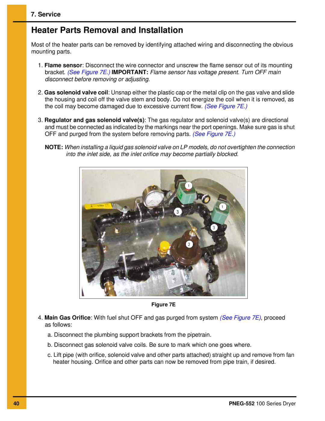
2.Gas solenoid valve coil: Unsnap either the plastic cap or the metal clip on the gas valve and slide the housing and coil off the valve stem and body. Do not energize the coil when it is removed, as the coil may become damaged due to excessive current flow. (See Figure 7E.)
3.Regulator and gas solenoid valve(s): The gas regulator and solenoid valve(s) are directional and must be connected as indicated by the markings near the port openings. Make sure gas is shut OFF and purged from the system before removing parts. (See Figure 7E.)
NOTE: When installing a liquid gas solenoid valve on LP models, do not overtighten the connection into the inlet side, as the inlet orifice may become partially blocked.
Figure 7E
4.Main Gas Orifice: With fuel shut OFF and gas purged from system (See Figure 7E), proceed as follows:
a.Disconnect the plumbing support brackets from the pipetrain.
b.Disconnect gas solenoid valve coils. Be sure to mark which one goes where.
c.Lift pipe (with orifice, solenoid valve and other parts attached) straight up and remove from fan heater housing. Orifice and other parts can now be removed from pipe train, if desired.
40