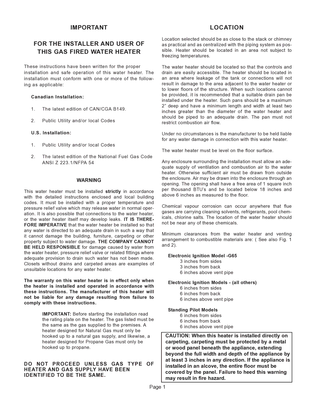
G65 specifications
The GSW G65 is a notable entry in the world of heavy-duty machinery, specifically designed for tasks that demand reliability and performance under challenging conditions. At the forefront of its features is a powerful engine that ensures optimal performance with robust torque delivery. This machine is equipped with a high-efficiency, state-of-the-art powertrain that maximizes productivity while minimizing fuel consumption.One of the standout characteristics of the GSW G65 is its exceptional lifting capacity, making it suitable for a variety of applications including construction, mining, and agricultural sectors. The G65 can lift and transport heavy loads with ease, enhancing operational efficiency. Safety is paramount, and the G65 incorporates advanced stability control systems, ensuring operators can work confidently even in difficult environments.
The GSW G65 also boasts cutting-edge technologies that elevate its performance standards. A sophisticated hydraulic system allows for smooth operation, enabling precise movements necessary for intricate tasks. This hydraulic innovation provides the machine with rapid response times and reduced downtime, vital components for any project requiring efficiency.
Furthermore, the G65 is designed with operator comfort in mind. The cabin includes ergonomic seating and intuitive controls, ensuring that operators can remain productive throughout their shifts without the burden of discomfort. Additionally, with advanced noise reduction features, the cabin environment is conducive to focus and safety.
Durability is a key attribute of the GSW G65. Built with high-strength materials, the machine is designed to withstand the rigors of demanding work environments. Its maintenance-friendly design allows for easy access to components, simplifying routine checks and servicing.
In terms of technology, the G65 comes equipped with a smart monitoring system that provides real-time feedback on performance metrics, helping operators stay informed of the machine's condition. This feature enhances preventative maintenance practices, reducing the likelihood of unexpected breakdowns.
Overall, the GSW G65 stands out as a formidable machine that blends power, efficiency, and advanced technology. Its robust features and focus on operator safety and comfort make it an indispensable tool in industries that require heavy lifting and reliability. The G65 is not just a machine; it represents a commitment to excellence and innovation in heavy-duty applications.

