GSW G65 Water Piping, Pressure Build-upin a Water System, Temperature and Pressure Relief Valve

Models: G65

1 24
Download 24 pages 14.74 Kb
Page 4
Image 4
WATER PIPING

WATER PIPING

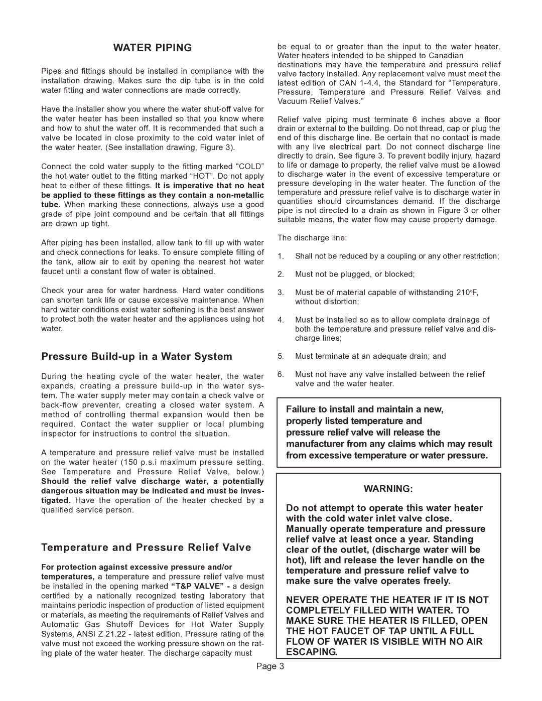
Pipes and fittings should be installed in compliance with the installation drawing. Makes sure the dip tube is in the cold water fitting and water connections are made correctly.

Have the installer show you where the water shut-off valve for the water heater has been installed so that you know where and how to shut the water off. It is recommended that such a valve be located in close proximity to the cold water inlet of the water heater. (See installation drawing, Figure 3).

Connect the cold water supply to the fitting marked “COLD” the hot water outlet to the fitting marked “HOT”. Do not apply heat to either of these fittings. It is imperative that no heat be applied to these fittings as they contain a non-metallic tube. When marking these connections, always use a good grade of pipe joint compound and be certain that all fittings are drawn up tight.

After piping has been installed, allow tank to fill up with water and check connections for leaks. To ensure complete filling of the tank, allow air to exit by opening the nearest hot water faucet until a constant flow of water is obtained.

Check your area for water hardness. Hard water conditions can shorten tank life or cause excessive maintenance. When hard water conditions exist water softening is the best answer to protect both the water heater and the appliances using hot water.

Pressure Build-up in a Water System

During the heating cycle of the water heater, the water expands, creating a pressure build-up in the water sys- tem. The water supply meter may contain a check valve or back-flow preventer, creating a closed water system. A method of controlling thermal expansion would then be required. Contact the water supplier or local plumbing inspector for instructions to control the situation.

A temperature and pressure relief valve must be installed on the water heater (150 p.s.i maximum pressure setting. See Temperature and Pressure Relief Valve, below.)

Should the relief valve discharge water, a potentially dangerous situation may be indicated and must be inves- tigated. Have the operation of the heater checked by a qualified service person.

Temperature and Pressure Relief Valve

For protection against excessive pressure and/or temperatures, a temperature and pressure relief valve must be installed in the opening marked “T&P VALVE” - a design certified by a nationally recognized testing laboratory that maintains periodic inspection of production of listed equipment or materials, as meeting the requirements of Relief Valves and Automatic Gas Shutoff Devices for Hot Water Supply Systems, ANSI Z 21.22 - latest edition. Pressure rating of the valve must not exceed the working pressure shown on the rat- ing plate of the water heater. The discharge capacity must

be equal to or greater than the input to the water heater. Water heaters intended to be shipped to Canadian destinations may have the temperature and pressure relief valve factory installed. Any replacement valve must meet the latest edition of CAN 1-4.4, the Standard for “Temperature, Pressure, Temperature and Pressure Relief Valves and Vacuum Relief Valves.”

Relief valve piping must terminate 6 inches above a floor drain or external to the building. Do not thread, cap or plug the end of this discharge line. Be certain that no contact is made with any live electrical part. Do not connect discharge line directly to drain. See figure 3. To prevent bodily injury, hazard to life or damage to property, the relief valve must be allowed to discharge water in the event of excessive temperature or pressure developing in the water heater. The function of the temperature and pressure relief valve is to discharge water in quantities should circumstances demand. If the discharge pipe is not directed to a drain as shown in Figure 3 or other suitable means, the water flow may cause property damage.

The discharge line:

1.Shall not be reduced by a coupling or any other restriction;

2.Must not be plugged, or blocked;

3.Must be of material capable of withstanding 210oF, without distortion;

4.Must be installed so as to allow complete drainage of both the temperature and pressure relief valve and dis- charge lines;

5.Must terminate at an adequate drain; and

6.Must not have any valve installed between the relief valve and the water heater.

Failure to install and maintain a new, properly listed temperature and pressure relief valve will release the manufacturer from any claims which may result from excessive temperature or water pressure.

WARNING:

Do not attempt to operate this water heater with the cold water inlet valve close. Manually operate temperature and pressure relief valve at least once a year. Standing clear of the outlet, (discharge water will be hot), lift and release the lever handle on the temperature and pressure relief valve to make sure the valve operates freely.

NEVER OPERATE THE HEATER IF IT IS NOT COMPLETELY FILLED WITH WATER. TO MAKE SURE THE HEATER IS FILLED, OPEN THE HOT FAUCET OF TAP UNTIL A FULL FLOW OF WATER IS VISIBLE WITH NO AIR ESCAPING.

Page 3

Page 4
Image 4
GSW G65 instruction manual Water Piping, Pressure Build-upin a Water System, Temperature and Pressure Relief Valve