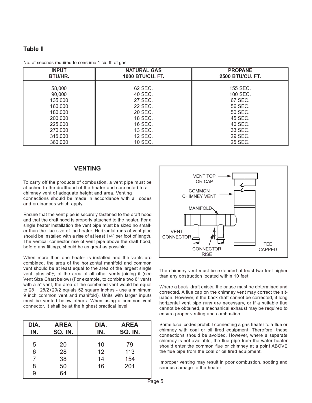
Table II

No. of seconds required to consume 1 cu. ft. of gas.


INPUT

NATURAL GAS

PROPANE

BTU/HR.

1000 BTU/CU. FT.

2500 BTU/CU. FT.

58,000

62 SEC.

155 SEC.

90,000

40 SEC.

100 SEC.

135,000

27 SEC.

67 SEC.

160,000

22 SEC.

56 SEC.

180,000

20 SEC.

50 SEC.

200,000

18 SEC.

45 SEC.

225,000

16 SEC.

40 SEC.

270,000

13 SEC.

33 SEC.

315,000

12 SEC.

29 SEC.

360,000

10 SEC.

25 SEC.

VENTING

To carry off the products of combustion, a vent pipe must be attached to the drafthood of the heater and connected to a chimney vent of adequate height and area. Venting connections should be made in accordance with all codes and ordinances which apply.

Ensure that the vent pipe is securely fastened to the draft hood and that the draft hood is properly attached to the heater. For a single heater installation the vent pipe must be sized no small- er than the flue size of the heater. Horizontal runs of vent pipe should be installed with a rise of at least 1/4” per foot of length. The vertical connector rise of vent pipe above the draft hood, before any fittings, should be as great as possible.

When more then one heater is installed and the vents are combined, the area of the horizontal manifold and common vent should be at least equal to the area of the largest single vent, plus 50% of the area of all other vents joining it (see Vent Size Chart below) (For example, to combine two 6” vents with a 5” vent, the area of the combined vent would be equal to 28 + 28/2+20/2 equals 52 square inches - use a minimum 9 inch common vent and manifold). Units with larger inputs must be vented below others. When using a common vent connector, it shall be at the highest practical level.

VENT TOP

OR CAP

COMMON

CHIMNEY VENT

MANIFOLD

VENT CONNECTOR

TEE

CONNECTORCAPPED RISE

The chimney vent must be extended at least two feet higher than any obstruction located within 10 feet.

Where a back draft exists, the cause must be determined and corrected. A flue cap on the chimney vent may correct the sit- uation. However, if the back draft cannot be corrected, if long horizontal vent pipe runs are necessary, or if a suitable flue cannot be obtained, a mechanical exhaust may be required to ensure proper venting and combustion.

DIA.

AREA

DIA.

AREA


Some local codes prohibit connecting a gas heater to a flue or

IN.

SQ. IN.

IN.

SQ. IN.


chimney with coal or oil fired equipment. Therefore, these


connections should be avoided. However, where a separate


5

20

10

79


chimney is not available, the flue pipe from the water heater


should enter the common flue or chimney at a point ABOVE

6

28

12

113


the flue pipe from the coal or oil fired equipment.

7

38

14

154


Improper venting may result in poor combustion, sooting and

8

50

16

201


serious damage to the heater.

9

64


Page 5


Page 6
Image 6
GSW G65 instruction manual Venting, DIA Area, Sq, Input Natural GAS Propane BTU/HR, 1000 BTU/CU. FT 2500 BTU/CU. FT

G65 specifications

The GSW G65 is a notable entry in the world of heavy-duty machinery, specifically designed for tasks that demand reliability and performance under challenging conditions. At the forefront of its features is a powerful engine that ensures optimal performance with robust torque delivery. This machine is equipped with a high-efficiency, state-of-the-art powertrain that maximizes productivity while minimizing fuel consumption.

One of the standout characteristics of the GSW G65 is its exceptional lifting capacity, making it suitable for a variety of applications including construction, mining, and agricultural sectors. The G65 can lift and transport heavy loads with ease, enhancing operational efficiency. Safety is paramount, and the G65 incorporates advanced stability control systems, ensuring operators can work confidently even in difficult environments.

The GSW G65 also boasts cutting-edge technologies that elevate its performance standards. A sophisticated hydraulic system allows for smooth operation, enabling precise movements necessary for intricate tasks. This hydraulic innovation provides the machine with rapid response times and reduced downtime, vital components for any project requiring efficiency.

Furthermore, the G65 is designed with operator comfort in mind. The cabin includes ergonomic seating and intuitive controls, ensuring that operators can remain productive throughout their shifts without the burden of discomfort. Additionally, with advanced noise reduction features, the cabin environment is conducive to focus and safety.

Durability is a key attribute of the GSW G65. Built with high-strength materials, the machine is designed to withstand the rigors of demanding work environments. Its maintenance-friendly design allows for easy access to components, simplifying routine checks and servicing.

In terms of technology, the G65 comes equipped with a smart monitoring system that provides real-time feedback on performance metrics, helping operators stay informed of the machine's condition. This feature enhances preventative maintenance practices, reducing the likelihood of unexpected breakdowns.

Overall, the GSW G65 stands out as a formidable machine that blends power, efficiency, and advanced technology. Its robust features and focus on operator safety and comfort make it an indispensable tool in industries that require heavy lifting and reliability. The G65 is not just a machine; it represents a commitment to excellence and innovation in heavy-duty applications.