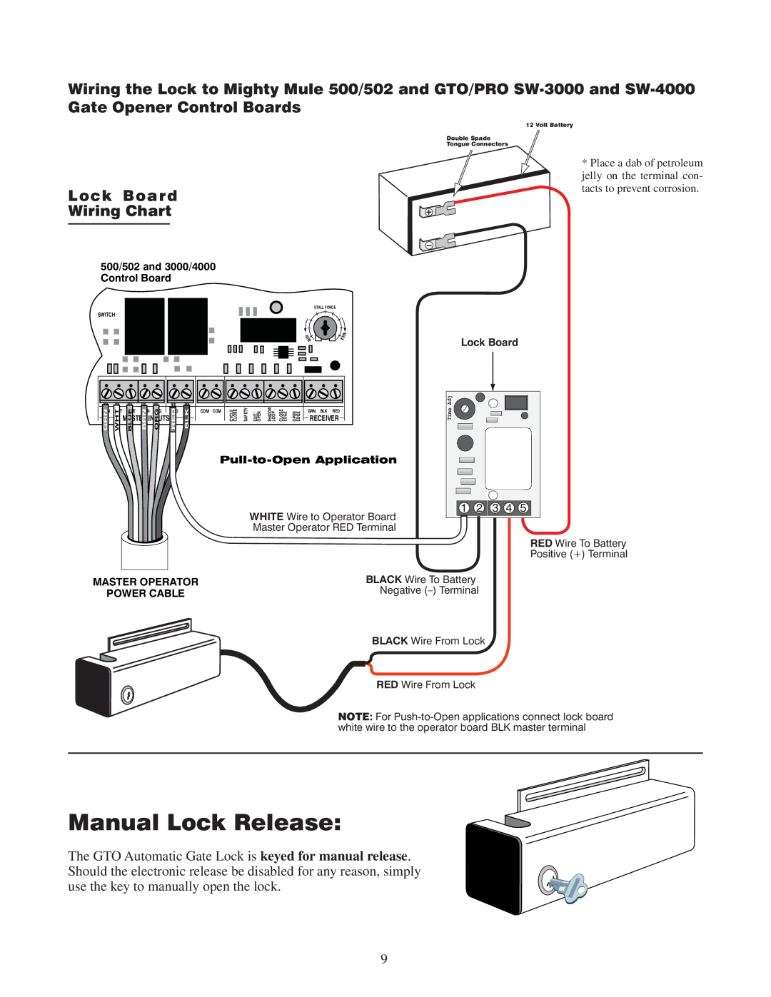
Wiring the Lock to Mighty Mule 500/502 and GTO/PRO
Gate Opener Control Boards
Lock Board
Wiring Chart
500/502 and 3000/4000 Control Board
| STALL FORCE |
SWITCH |
|
N | M |
I | A |
M | X |
12 Volt Battery
Double Spade
Tongue Connectors
* Place a dab of petroleum jelly on the terminal con- tacts to prevent corrosion.
Lock Board
GRN | WHT | BLUE | BRN | ORG | RED | BLK | COM | COM |
| SAFETY |
| SHADOW LOOP |
|
| GRN | BLK | RED |
GRN | WHT | MASTER INPUTS | RED | BLK |
|
| CYCLE CLOSE |
| CLOSE EDGE |
| RECEIVER | ||||||
BLUE | BRN | ORG |
|
| EXIT/ OPEN | OPEN EDGE |
|
|
| ||||||||
Time Adj
WHITE Wire to Operator Board Master Operator RED Terminal
1 2 3 4 5
RED Wire To Battery
Positive (+) Terminal
MASTER OPERATOR
POWER CABLE
BLACK Wire To Battery
Negative
BLACK Wire From Lock
RED Wire From Lock
NOTE: For
Manual Lock Release:
The GTO Automatic Gate Lock is keyed for manual release. Should the electronic release be disabled for any reason, simply use the key to manually open the lock.
9