Wiring the Lock to Mighty Mule
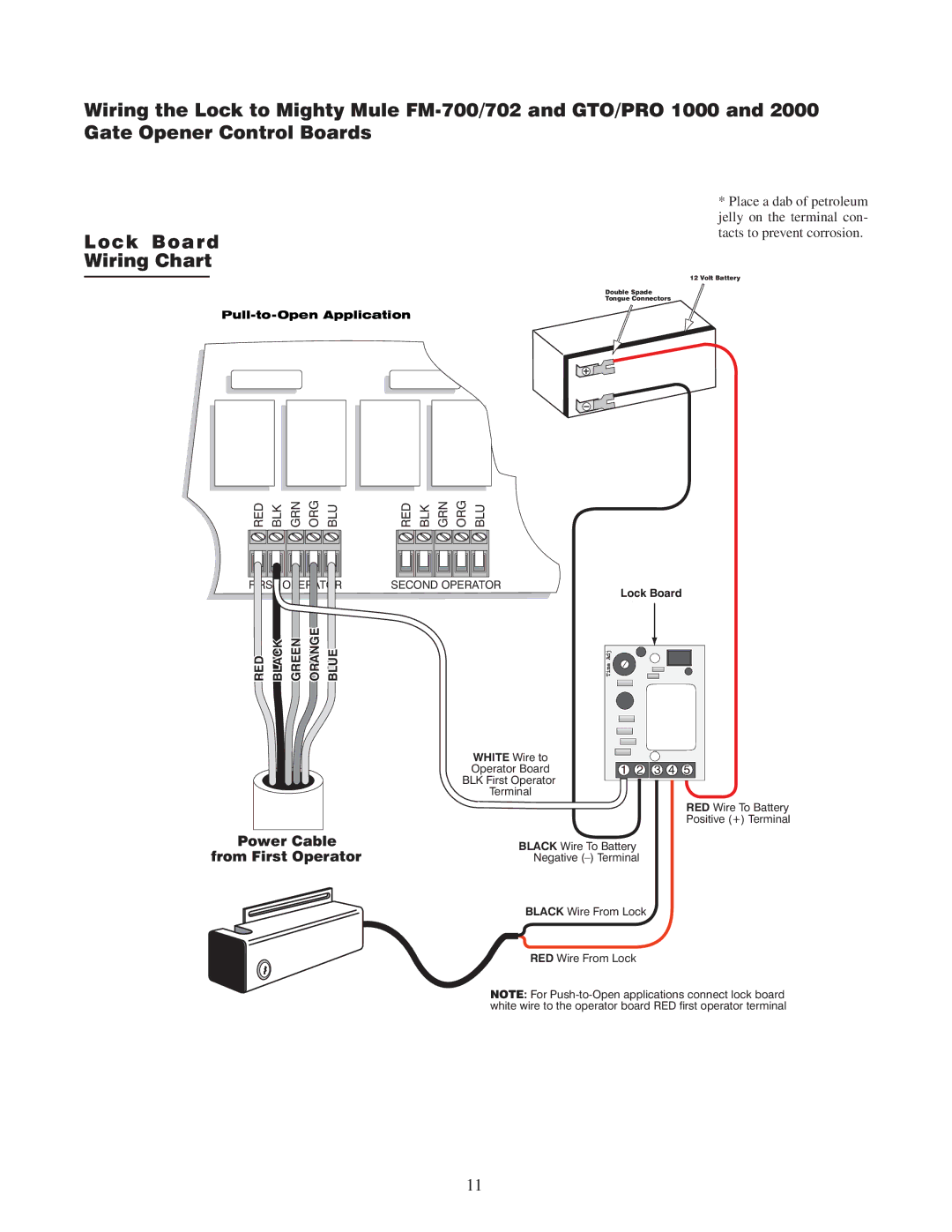
Lock Board
Wiring Chart
1515
RED BLK GRN ORG BLU | RED BLK GRN ORG BLU |
FIRST OPERATOR | SECOND OPERATOR |
RED BLACK GREEN ORANGE BLUE |
|
WHITE Wire to
Operator Board
BLK First Operator
Terminal
*Place a dab of petroleum jelly on the terminal con- tacts to prevent corrosion.
12 Volt Battery
Double Spade
Tongue Connectors
Lock Board
Adj
Time
1 2 ![]()
![]() 3 4 5
3 4 5
RED Wire To Battery
Positive (+) Terminal
Power Cable from First Operator
BLACK Wire To Battery
Negative
BLACK Wire From Lock
RED Wire From Lock
NOTE: For
11