Switch Hardware
3.2.2.1.8Power LED
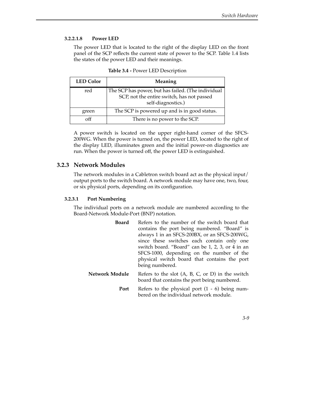
The power LED that is located to the right of the display LED on the front panel of the SCP reflects the current state of power to the SCP. Table 1.4 lists the states of the power LED and their meanings.
| Table 3.4 - Power LED Description |
|
|
LED Color | Meaning |
|
|
red | The SCP has power, but has failed. (The individual |
| SCP, not the entire switch, has not passed |
| |
|
|
green | The SCP is powered up and is in good status. |
|
|
off | There is no power to the SCP. |
|
|
A power switch is located on the upper
3.2.3 Network Modules
The network modules in a Cabletron switch board act as the physical input/ output ports to the switch board. A network module may have one, two, four, or six physical ports, depending on its configuration.
3.2.3.1Port Numbering
The individual ports on a network module are numbered according to the
Board Refers to the number of the switch board that contains the port being numbered. “Board” is always 1 in an
Network Module Refers to the slot (A, B, C, or D) in the switch board that contains the port being numbered.
Port Refers to the physical port (1 - 6) being num- bered on the individual network module.
