Switch Hardware
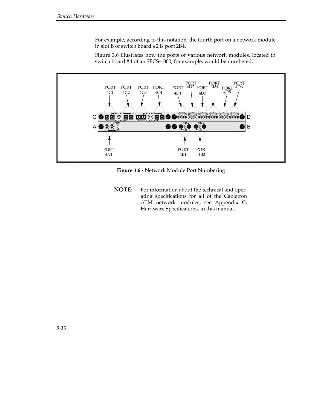
For example, according to this notation, the fourth port on a network module in slot B of switch board #2 is port 2B4.
Figure 3.6 illustrates how the ports of various network modules, located in switch board #4 of an SFCS-1000, for example, would be numbered.
|
|
|
|
|
| PORT |
| PORT | PORT | |
PORT | PORT | PORT | PORT | PORT | 4D2 PORT 4D4 | PORT 4D6 | ||||
4C1 | 4C2 | 4C3 | 4C4 | 4D1 |
| 4D3 |
| 4D5 | ||
|
|
|
|
|
|
|
|
|
|
|
RX1 RX2 | RX3 RX4 | T1 | R1 | T2 | R2 T3 | R3 T4 | R4 | T5 | R5 T6 | R6 |
C |
|
|
|
|
|
|
|
|
| D |
TX1 TX2 | TX3 TX4 |
|
|
|
|
|
|
|
|
|
RX1 |
|
| RX1 |
| RX2 |
|
|
|
| B |
A |
|
| TX1 |
| TX2 |
|
|
|
| |
TX1 |
|
|
|
|
|
|
|
|
PORT | PORT | PORT |
4A1 | 4B1 | 4B2 |
Figure 3.6 - Network Module Port Numbering
NOTE: For information about the technical and oper- ating specifications for all of the Cabletron ATM network modules, see Appendix C, Hardware Specifications, in this manual.