Switch Hardware
3.2.7.3.2Power Supply LEDs
There are two power supply LEDs on the front panel of the CEC, one for each power supply. The LEDs for the two power supplies should be illuminated yellow, indicating that the CEC is on and that the power supply correspond- ing to that LED is functioning correctly. The LED for a failed power supply will be extinguished. On an SFCS-1000, power supply “1” is in the slot labeled PS1 on the enclosure, while power supply “2” is in the slot labeled PS2 on the enclosure.
3.2.7.3.3Switch Board LEDs
There are four switch board LEDs on the front panel of the CEC, one for each possible switch board. These LEDs should be blinking, indicating that the switch has booted and is operating correctly. If the SCP is removed, the LEDs may remain in a steady-on or steady-off state. Even if the SCP has booted cor- rectly, the LEDs will not illuminate if the SCP is running a software version prior to 3.2.0. If the switch board in the slot corresponding to the LED is not intended for an SFCS-1000 (e.g., it is an SFCS-200BX board), or if the entire switch board corresponding to that LED is removed, then that LED will be extinguished. On an SFCS-1000, the SW1 LED corresponds to switch board “1,” which is in the slot labeled 1 on the enclosure, and so on.
3.2.7.4Ethernet Port
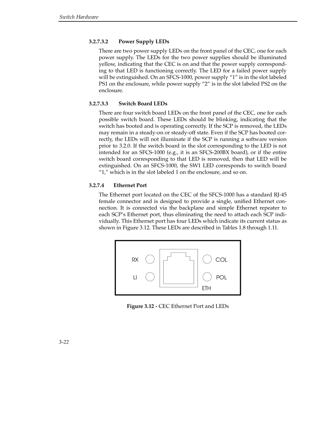
The Ethernet port located on the CEC of the SFCS-1000 has a standard RJ-45 female connector and is designed to provide a single, unified Ethernet con- nection. It is connected via the backplane and simple Ethernet repeater to each SCP’s Ethernet port, thus eliminating the need to attach each SCP indi- vidually. This Ethernet port has four LEDs which indicate its current status as shown in Figure 3.12. These LEDs are described in Tables 1.8 through 1.11.
Figure 3.12 - CEC Ethernet Port and LEDs
3-22

