Switch Hardware
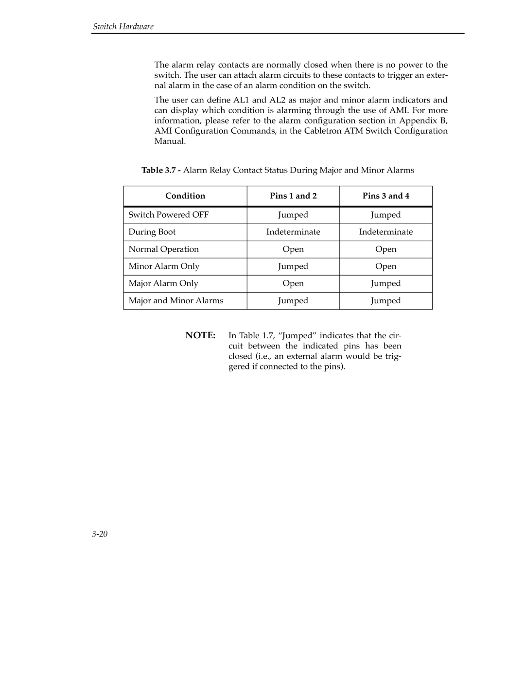
The alarm relay contacts are normally closed when there is no power to the switch. The user can attach alarm circuits to these contacts to trigger an exter- nal alarm in the case of an alarm condition on the switch.
The user can define AL1 and AL2 as major and minor alarm indicators and can display which condition is alarming through the use of AMI. For more information, please refer to the alarm configuration section in Appendix B, AMI Configuration Commands, in the Cabletron ATM Switch Configuration Manual.
Table 3.7 - Alarm Relay Contact Status During Major and Minor Alarms
Condition |
| Pins 1 and 2 |
| Pins 3 and 4 |
|
|
|
|
|
Switch Powered OFF |
| Jumped |
| Jumped |
|
|
|
|
|
During Boot |
| Indeterminate |
| Indeterminate |
|
|
|
|
|
Normal Operation |
| Open |
| Open |
|
|
|
|
|
Minor Alarm Only |
| Jumped |
| Open |
|
|
|
|
|
Major Alarm Only |
| Open |
| Jumped |
|
|
|
|
|
Major and Minor Alarms |
| Jumped |
| Jumped |
|
|
|
| |
NOTE: | In Table 1.7, “Jumped” indicates that the cir- | |||
| cuit between the indicated pins has been | |||
| closed (i.e., an external alarm would be trig- | |||
| gered if connected to the pins). |
| ||
