Hardware Specifications
C.2.5.3 Connecting Adapters with Token Ring Pinouts to Cabletron Switches
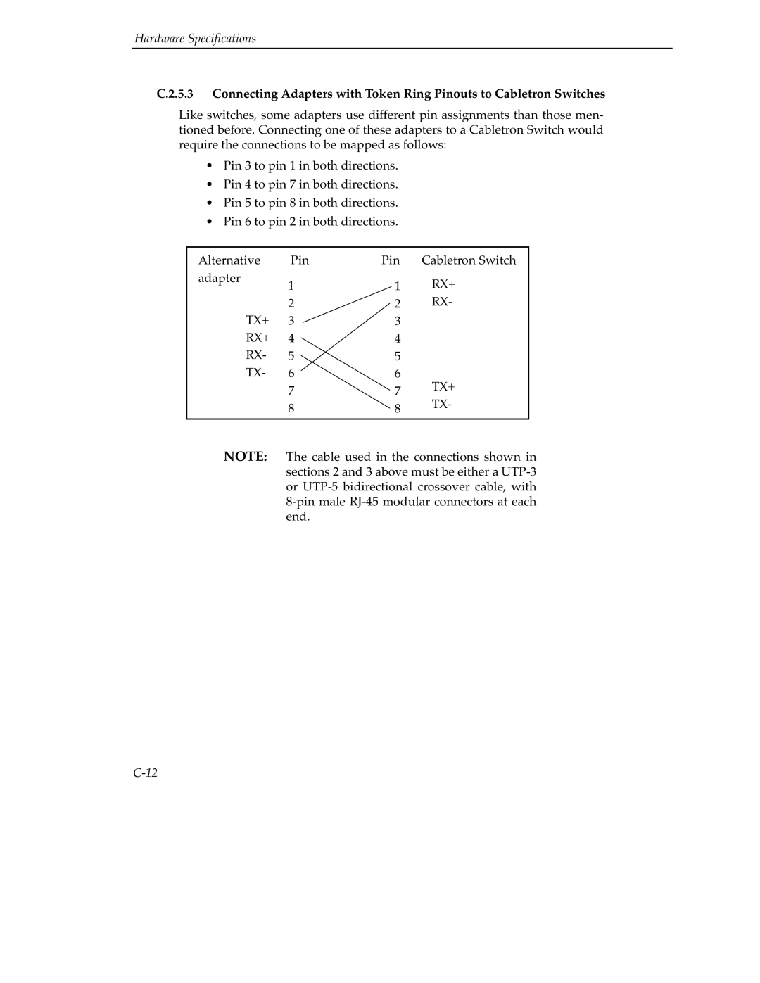
Like switches, some adapters use different pin assignments than those men- tioned before. Connecting one of these adapters to a Cabletron Switch would require the connections to be mapped as follows:
•Pin 3 to pin 1 in both directions.
•Pin 4 to pin 7 in both directions.
•Pin 5 to pin 8 in both directions.
•Pin 6 to pin 2 in both directions.
Alternative | Pin | Pin | Cabletron Switch |
adapter | 1 | 1 | RX+ |
| |||
| 2 | 2 | RX- |
TX+ | 3 | 3 |
|
RX+ | 4 | 4 |
|
RX- | 5 | 5 |
|
TX- | 6 | 6 | TX+ |
| 7 | 7 | |
| TX- | ||
| 8 | 8 | |
|
| ||
|
|
|
|
NOTE: The cable used in the connections shown in sections 2 and 3 above must be either a