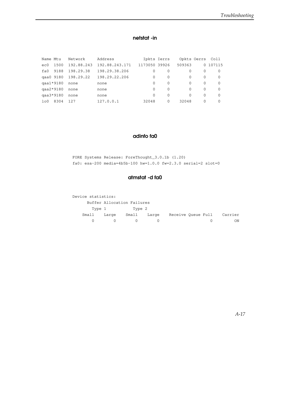
MMAC-Plus 9A000, SFCS-200BX
SFCS-200WG and SFCS-1000 ATM SWITCH User’s Guide
Page
Copyright April 1996 by Cabletron Systems, Inc 35 Industrial Way
VCCI Notice
FCC Notice
Installing the 9A000
Table of Contents
Switch Hardware
Preface
Hardware Maintenance Procedures
Switch Setup
Contents
Chapter
Appendix A
Software Upgrade Instructions
Appendix B
Troubleshooting
Contents
Appendix C
Hardware Specifications
Typographical Styles
PREFACE
Technical Support
PREFACE
Important Information Indicators
viii
Are all four conditions true?
Information contained in NOTE statements has been found important enough to be called to the special attention of the operator and will be set off from the text as follows
PREFACE
PREFACE
Laser Warning
Safety Precautions
Safety Agency Compliance
Symbols
PREFACE
Power Cord Connection
Placement of a Cabletron Systems Product
Modifications to Equipment
PREFACE
1.1 Overview of the ATM Standard
CHAPTER
Introduction
Introduction
1.2 Hardware Description
Introduction
Figure 1.1 - 9A000 Switch Configuration
1.2.1 Front Panel Description
1.2.3 9A000 and SFCS Series Switch Board
1.2.2 9A000 and SFCS Series Hardware Configuration
Introduction
1.2.5 9A000 and SFCS Series Network Modules
1.2.4 Switch Control Processor
1.2.6 Environmental Information
Introduction
Introduction
Features
1.3.1 Switch Control Software
1.2.8 Safety Compliance
1.3 Software Description
1.2.7 Standards Compliance
Introduction 1-8
CHAPTER
Installing the 9A000
2.1 Installing the 9A000
Jack for ESD wrist strap Metal Back-Panel Circuit Card Card Guides
Installing the 9A000
Ensure that the circuit card is between the card guides
Figure 2.1 - Installing the 9A000 Module
Installing the 9A000
2.2 The Reset Switch
Installing the 9A000 2-4
CHAPTER
Switch Hardware
Switch Hardware
3.1 Switch Hardware Configurations
Figure 3.2 - SFCS-200BX Switch Configuration
Switch Hardware
48V DC
Switch Hardware
AC Volt. In
SFCS
3.2.1 Switch Board
3.2 Switch Hardware Components
3.2.2 Switch Control Processor
Switch Hardware
3.2.2.1 i960 Switch Control Processor
Switch Hardware
3.2.2.1.1 RESET Button
3.2.2.1.2 RS-232 Serial Port
Signal
Switch Hardware
Signal Name
Pin Number
3.2.2.1.4 CTL Port
Switch Hardware
3.2.2.1.5 NEXT Pushbutton
3.2.2.1.6 SELECT Pushbutton
Switch Hardware
3.2.3 Network Modules
3.2.2.1.8 Power LED
LED Color
Switch Hardware
3-10
3-11
3.2.4 Power Supply Modules
Switch Hardware
3.2.4.1 SFCS-200BX AC Power Supply
Switch Hardware
3-12
3.2.4.2 SFCS-1000 AC Power Supply Model A
The model A AC power supply for an SFCS-1000 is shown in Figure
Switch Hardware
3-13
3.2.4.2.1 Power Supply LEDs
3.2.4.2.2 Shutdown Conditions
If a model A power supply goes into shutdown, it will remain shut down until the power switch is turned off and turned on again power cycle. The power switch must remain off long enough for the SHUTDOWN LED to extinguish this allows the capacitors to discharge
3-14
Switch Hardware
Switch Hardware
3-15
3.2.4.3 SFCS-1000 AC Power Supply Model B
The model B AC power supply for an SFCS-1000 is shown in Figure
Switch Hardware
3-16
3.2.4.3.1 Power Supply LEDs
3.2.4.3.2 Shutdown Conditions
Switch Hardware
3-17
3.2.5 SFCS-1000 Fan Tray
3.2.6 SFCS-1000 Temperature Sensing
3-18
Switch Hardware
3-19
3.2.7 SFCS-1000 Common Equipment Card CEC
Switch Hardware
AL1AL2
Switch Hardware
3-20
Pins 1 and
Pins 3 and
Switch Hardware
3-21
3.2.7.3.1 Alarm LEDs
3.2.7.3 CEC Status LEDs
Switch Hardware
3-22
3.2.7.3.2 Power Supply LEDs
3.2.7.3.3 Switch Board LEDs
Switch Hardware
3-23
LED Color
Meaning
Switch Hardware 3-24
4.1 Introduction
Switch Setup
4.2 Unpacking
CHAPTER
4.2.1 Inventorying the Unit
Switch Setup
Switch Setup
4.3 Electrical Considerations
Switch Setup
4.4 Rack-Mounting an SFCS-200BX
4.4.1 Required Tools
Switch Setup
4.4.2 Installing the Rack-mount Brackets
NOTE The SFCS-200BX is an operational ATM switch at this point if used with other Cabletron switches or with ATM interface cards. However, if other vendor equipment is connected, you may have to complete an ini- tial user configuration
Switch Setup
Switch Setup
4.5 Rack-Mounting an SFCS-200WG
4.5.1 Required Tools
Switch Setup
4.5.2 Installing the Rack-mount Brackets
Switch Setup
Switch Setup
4.6 Rack-Mounting an SFCS-1000
4-10
Switch Setup
4.6.1 Installing the SFCS-1000
4-11
Switch Setup
4.7 Installing the Serial Cable
4-12
4.8.1 Modem Parameters
4.8 Modem Configuration
4-13
Switch Setup
configuration ip address interface address
4.9 Configuring IP Addresses
configuration ip mask interface mask
4-14
4.11 Subsequent Operation
4.10 AMI Security
4-15
Switch Setup
4.13 Product Registration Information
4.12 Verifying the Installation
configuration port show
4-16
5.1 Network Module Replacement
Hardware Maintenance Procedures
5.1.1 Overview
CHAPTER
Hardware Maintenance Procedures
5.1.2 Multicast Mode
Hardware Maintenance Procedures
5.1.3 Hot-swapping Network Modules
Hardware Maintenance Procedures
5.2 Power Supply Module Replacement
5.2.1 SFCS-200BX Power Supply Module Replacement
5. Pull forward on the handle to remove the sliding tray
Hardware Maintenance Procedures
5.2.2 SFCS-1000 Power Supply Module Replacement
5.2.2.1 Replacing an SFCS-1000 AC Power Supply Model A
AC 48V DC 5VDC OK SHUTDOWN
3. Unplug and remove the power cord from the failed supply
Hardware Maintenance Procedures
7. Ensure that the fuses on the new unit are rated at 12.5A
Hardware Maintenance Procedures
5.2.2.2 Replacing an SFCS-1000 AC Power Supply Model B
Hardware Maintenance Procedures
A model B AC power supply module for an SFCS-1000 is shown in Figure
ON/OFF Switch Handle
Hardware Maintenance Procedures
5-10
6. Set the failed supply aside and prepare to install the new one
5-11
Hardware Maintenance Procedures
5.3 SFCS-1000 Fan Tray Replacement
5-12
Hardware Maintenance Procedures
5.4 Switch Control Processor Replacement
5-13
CAUTION Take care to properly align the SCP in the card guides in the following step
5-14
Hardware Maintenance Procedures
5.5 Switch Board Replacement
5-15
NOTE To ensure that the switch will work with the previously established network configuration, the relative position of the network modules must not change when you transfer them to the new fabric. For example, an OC-3c network module that is removed from slot A of the old switch fabric must be installed in slot A of the new switch fabric. Therefore, it is recommended that you label all network connections and network modules before removing them
5-16
Hardware Maintenance Procedures
CAUTION Make sure the replacement board is properly aligned in the slot in the next step
5-17
Hardware Maintenance Procedures
Hardware Maintenance Procedures 5-18
CHAPTER
Software Upgrade Instructions
6.1 Obtaining the Software Upgrade File via Diskette
tar -xvf device
eject device
Software Upgrade Instructions
foreextract device
mkdir /tftpboot
6.2 Performing the Software Upgrade
mv filename /tftpboot
operation upgrade ?
Software Upgrade Instructions
operation upgrade 169.144.3.54asx-scp4.0.01.3
operation upgrade 169.144.3.54ASX-200BX4.0.01.3
Reboot the switchy? y
Software Upgrade Instructions
6.3 Changing between Multiple Versions of Software
Are you sure you want to reboot this switch n? y
Software Upgrade Instructions
localhostoperation reboot
6.4.2 Setting Up Your bootp Server
6.4 Using bootp to Download Software to the Switch
6.4.1 Overview
Software Upgrade Instructions
6.4.3 Adding an Entry for Your Switch in the bootptab File
6-10
The variables in the previous example are defined as follows
6-11
Software Upgrade Instructions
6.4.4 Setting Up a tftpboot Server
6-12
APPENDIX A
Troubleshooting
A.1 Adapter Hardware Troubleshooting
Figure A.1 - Adapter Hardware Troubleshooting Flowchart
Troubleshooting
Troubleshooting
A.1.1 Run Looptest
Troubleshooting
A.1.2 Check Self-Test Automatically Performed
A.1.3 Firmware Download Automatically Performed
Troubleshooting
A.1.4 Hardware Detected by Driver
netstat
Troubleshooting
A.1.5 Check Firmware
atmstat fa0
Troubleshooting
A.1.6 Check Physical Link
Troubleshooting
A.2 Testing Network Connectivity Using PVCs
Figure A
Troubleshooting
ping IPaddressofremoteworkstation
A-10
Troubleshooting
A.2.1 Verifying the Outgoing ATM ARP Entry
A-11
Troubleshooting
A.2.2 atmstat
A-12
Troubleshooting
A-13
A.2.2.2 Cells and VPI/VCI Errors Received by Remote
A.2.2.3 Cells and AAL* Errors Received by Remote
A.2.2.5 Cells and No Errors Received by Remote and Transmitting Cells
A-14
Troubleshooting
A.3.1 Basic Information
A.3 Collecting Additional Information
A.3.2 Adapter Information
A-15
ifconfig fa0
uname -a
netstat -nr
A-16
adinfo fa0
netstat -in
A-17
Troubleshooting
Troubleshooting
A.3.3 Switch Information
A-18
cport switchname
asxmon switchname
A-19
Troubleshooting
configuration port show
configuration spans show
A-20
Troubleshooting
configuration port ds3 show
configuration port taxi show
A-21
Troubleshooting
configuration port sonet show
configuration port ds1 show
configuration e1 show
configuration port e3 show
APPENDIX B
SCP Diagnostics
B.1 SFCS-200WG, SFCS-200BX, SFCS-1000 Diagnostics
SCP Diagnostics
B.1.1 Accessing the Monitor Mode
SCP Diagnostics
SCP Diagnostics
B.1.2 Running the Hardware Tests
B.1.2.1 Clock Test
B.1.2.2 DRAM Test
B.1.2.3 DRAM Chip Test
SCP Diagnostics
B.1.2.4 Ethernet Test
B.1.2.5 FLASH Test
=test-fc 1 Save Chip
SCP Diagnostics
B.1.2.6 FLASH Chip Test
B.1.2.9 Timer Test
SCP Diagnostics
Timer OK
Clock OK DRAM OK Ethernet OK Timer OK Serial OK
B.1.2.11 Complete Hardware Test
SCP Diagnostics
=test-manufact Clock OK DRAM OK Ethernet OK Timer OK
Hardware Specifications
C.1 Cabletron ATM Switches
APPENDIX C
C.1.1 SFCS-200WG
Hardware Specifications
C.1.2 SFCS-200BX
Hardware Specifications
C.1.3 SFCS-1000
Hardware Specifications
C.2 ATM Network Modules
C.2.1 100 Mbps TAXI Module
Hardware Specifications
C.2.2 155 Mbps OC-3c/STM-1 MM Module
Hardware Specifications
C.2.3 155 Mbps STS-3c/STM-1 UTP Module
Signal
Hardware Specifications
Signal Name
C.2.3.2 Connecting Switches with 155 Mbps UTP Network Modules
Hardware Specifications
C.2.4 622 Mbps OC-12c/STM-4c MM Module
Hardware Specifications
C.2.5 25 Mbps TP25 Module
C-10
C.2.5.1 Connecting Switches with TP25 Network Modules
C-11
Hardware Specifications
C-12
Hardware Specifications
C.2.6 34 Mbps E3 Module
C-13
Hardware Specifications
C.2.7 45 Mbps DS3 Module
C-14
Hardware Specifications
C.2.8 155 Mbps OC-3c/STM-1 SM Module
C-15
Hardware Specifications
C.2.9 155 Mbps OC-3c/STM-1 3MM/1SM Module
C-16
Description
C-17
Hardware Specifications
C.2.10 622 Mbps OC-12c/STM-4c SM Module
C-18
C.3.1 Adapter Cabling Specifications
C.3 ATM Adapters
C-19
Hardware Specifications
C.3.1.2 UTP Cable Specifications
C-20
Hardware Specifications
C.3.2 ESA-200PC Technical Specifications
C-21
Hardware Specifications
C.3.3 PCA-200PC Technical Specifications
C-22
Hardware Specifications
C.3.4 PCA-200MAC Technical Specifications
C-23
Hardware Specifications
C.3.5 NBA-200 Technical Specifications
C-24
Hardware Specifications
C.3.6 GIA-200 Technical Specifications
C-25
Hardware Specifications
C.3.7 HPA-200 Technical Specifications
C-26
Hardware Specifications
C.3.8 MCA-200 Technical Specifications
C-27
Hardware Specifications
C.3.9 SBA-200 Technical Specifications
C-28
Hardware Specifications
C.3.10 ESA-200 Technical Specifications
C-29
Hardware Specifications
C.3.11 VMA-200 Technical Specifications
C-30
Hardware Specifications C-31
Hardware Specifications C-32
GLOSSARY
ATM Link - a virtual path link VPL or a virtual channel link VCL
GLOSSARY
GLOSSARY
atmconfig - a FORE program used to enable or disable SPANS signalling
Cell - an ATM Layer protocol data unit PDU
GLOSSARY
Cell Header - ATM Layer protocol control information
GLOSSARY
DSn Digital Standard n 0, 1, 1C, 2, and 3 - a method that defines the rate and format of digital hierarchy
GLOSSARY
EPROM - Erasable Programmable Read Only Memory See PROM
GLOSSARY
HPUX - the Hewlett-Packard version of UNIX
GLOSSARY
nnn.nnn.nnn.nnn
GLOSSARY
GLOSSARY
g-10
Layer Entity - an active layer within an element
g-11
GLOSSARY
GLOSSARY
g-12
OpenView - Hewlett-Packard’s network management software
g-13
GLOSSARY
Peer Entities - entities within the same layer
g-14
GLOSSARY
Point-to-Point Connection - a connection with only two endpoints
g-15
GLOSSARY
PVC Permanent Virtual Circuit or Channel - a circuit or channel through an ATM network provisioned by a carrier between two endpoints used for dedicated long-term information transport between locations
g-16
GLOSSARY
SGMP Simple Gateway Management Protocol - the predecessor to SNMP
g-17
GLOSSARY
GLOSSARY
g-18
STS Synchronous Transport Signal - a SONET electrical signal rate
GLOSSARY
g-19
Switched Connection - a connection established via signalling
VCI Virtual Channel Identifier - the address or label of a VC
g-20
GLOSSARY
VPI Virtual Path Identifier - the address or label of a particular VP
g-21
GLOSSARY
GLOSSARY g-22