Troubleshooting
A.1.6 Check Physical Link
To see the carrier state of the board, issue the following command:
atmstat -d fa0
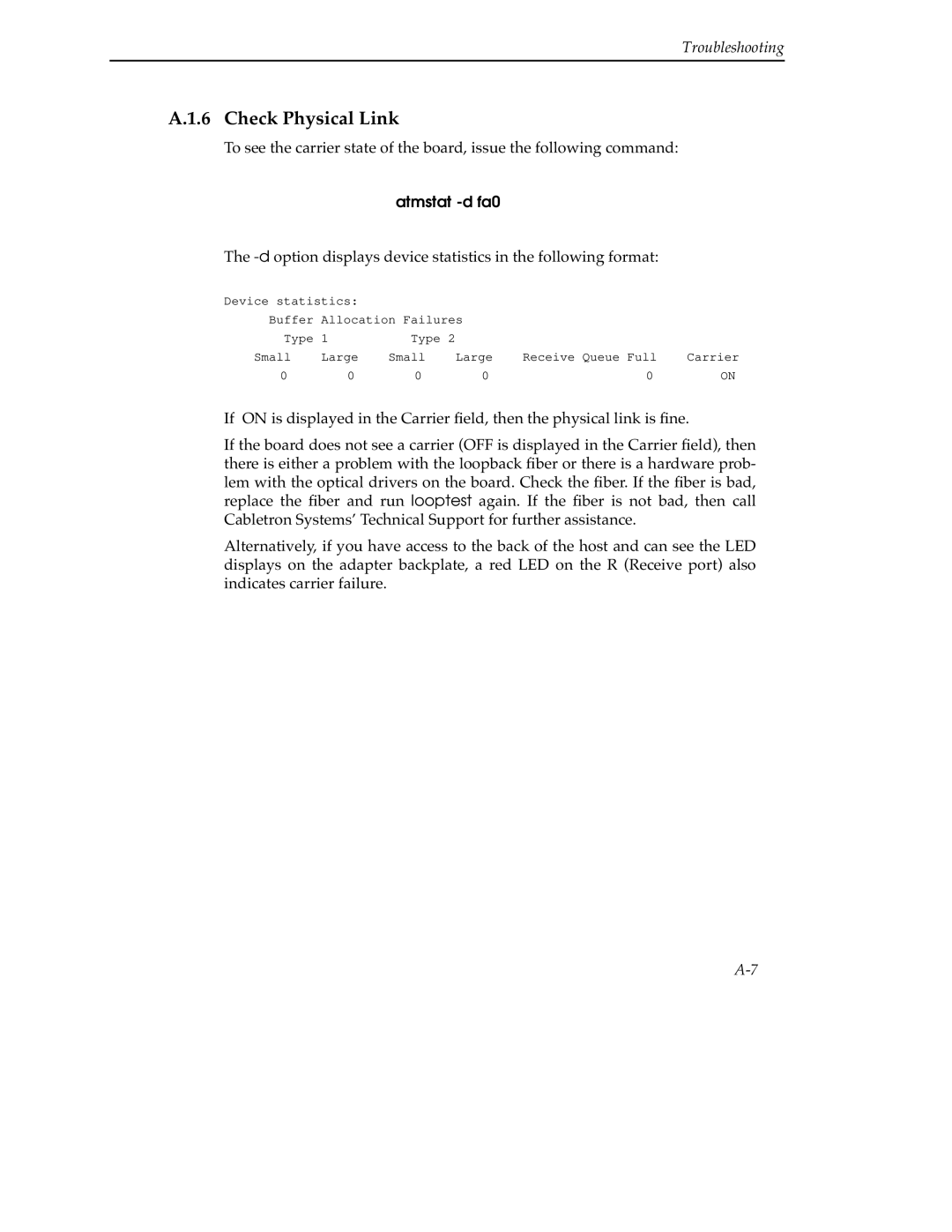
The -d option displays device statistics in the following format:
Device statistics: |
|
|
|
| |
Buffer Allocation Failures |
|
| |||
Type | 1 | Type 2 |
|
|
|
Small | Large | Small | Large | Receive Queue Full | Carrier |
0 | 0 | 0 | 0 | 0 | ON |
If ON is displayed in the Carrier field, then the physical link is fine.
If the board does not see a carrier (OFF is displayed in the Carrier field), then there is either a problem with the loopback fiber or there is a hardware prob- lem with the optical drivers on the board. Check the fiber. If the fiber is bad, replace the fiber and run looptest again. If the fiber is not bad, then call Cabletron Systems’ Technical Support for further assistance.
Alternatively, if you have access to the back of the host and can see the LED displays on the adapter backplate, a red LED on the R (Receive port) also indicates carrier failure.