Design Features – SR2300CE, SR2800CE
PIN SPKR
1+ CHA+
1- CHA-
2+ CHB+
2- CHB-
|
| Audio GND | |
|
|
| CH A |
CH A | CH A |
| OUT |
| (MONO) | ||
IN | BIAMP STEREO BUFFER | Chassis | Float |
THRU
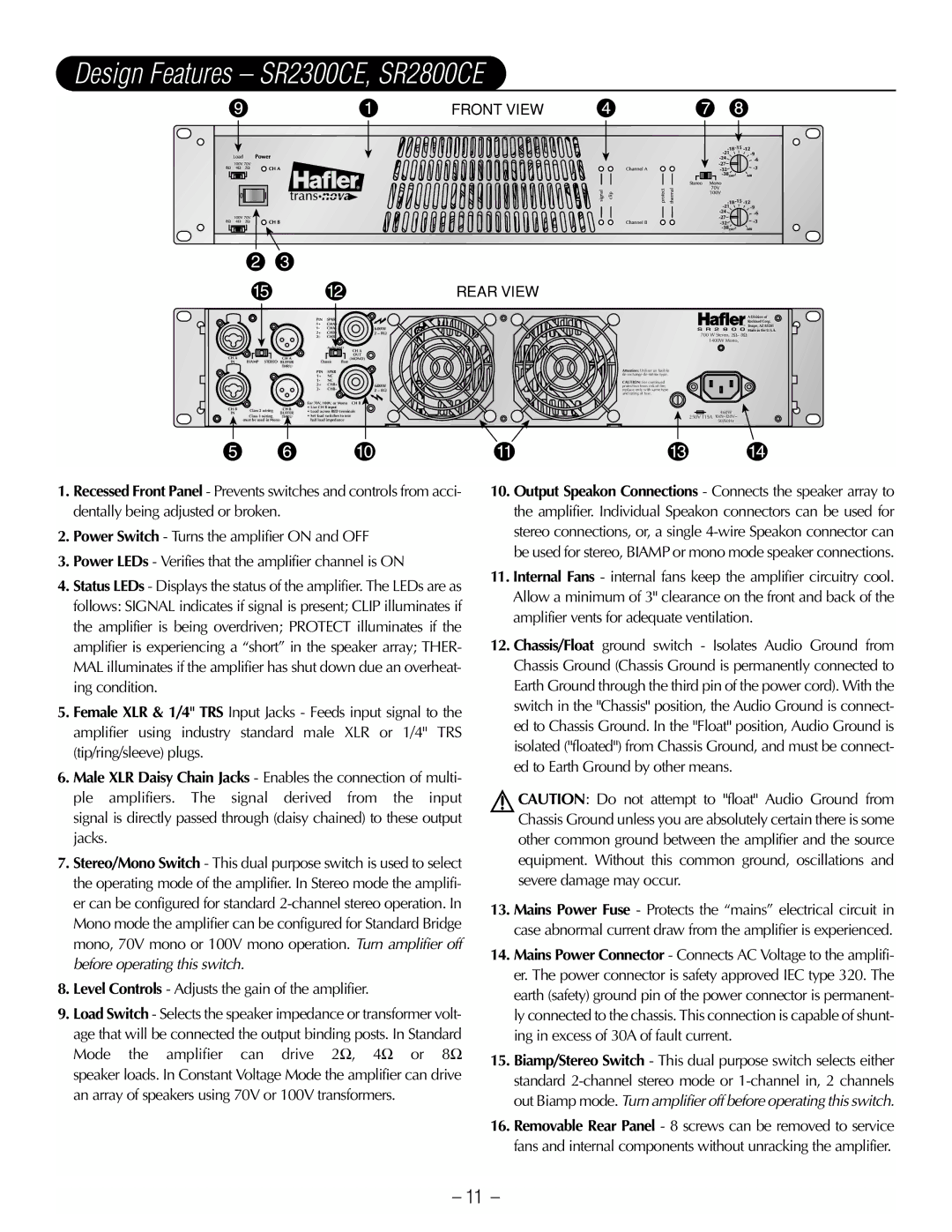
FRONT VIEW
REAR VIEW
| A Division of |
| Rockford Corp. |
® | Tempe, AZ 85281 |
S R 2 8 0 0 | Made in the U.S.A. |
700 W Stereo, 2Ω– 8Ω
1400W Mono,
Attention: Utiliser un fusible de rechange de même type.
CAUTION: For continued protection from risk of fire, replace only with same type and rating of fuse.
460W
250V T15A
10.Output Speakon Connections - Connects the speaker array to the amplifier. Individual Speakon connectors can be used for stereo connections, or, a single
11.Internal Fans - internal fans keep the amplifier circuitry cool. Allow a minimum of 3" clearance on the front and back of the amplifier vents for adequate ventilation.
12.Chassis/Float ground switch - Isolates Audio Ground from Chassis Ground (Chassis Ground is permanently connected to Earth Ground through the third pin of the power cord). With the switch in the "Chassis" position, the Audio Ground is connect- ed to Chassis Ground. In the "Float" position, Audio Ground is isolated ("floated") from Chassis Ground, and must be connect- ed to Earth Ground by other means.
!CAUTION: Do not attempt to "float" Audio Ground from Chassis Ground unless you are absolutely certain there is some other common ground between the amplifier and the source equipment. Without this common ground, oscillations and severe damage may occur.
13.Mains Power Fuse - Protects the “mains” electrical circuit in case abnormal current draw from the amplifier is experienced.
14.Mains Power Connector - Connects AC Voltage to the amplifi- er. The power connector is safety approved IEC type 320. The earth (safety) ground pin of the power connector is permanent- ly connected to the chassis. This connection is capable of shunt- ing in excess of 30A of fault current.
15.Biamp/Stereo Switch - This dual purpose switch selects either standard
16.Removable Rear Panel - 8 screws can be removed to service fans and internal components without unracking the amplifier.
– 11 –