Name of Parts
10 11
3
9
8
Fig.1
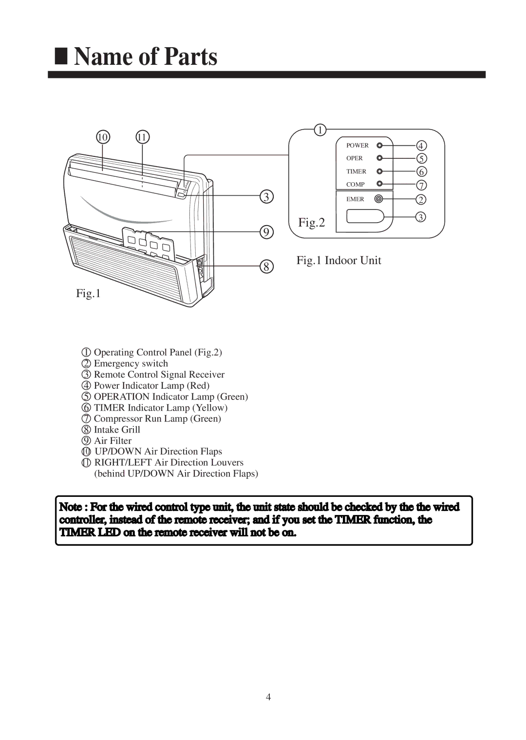
1Operating Control Panel (Fig.2)
2Emergency switch
3Remote Control Signal Receiver
4Power Indicator Lamp (Red)
5OPERATION Indicator Lamp (Green)
6TIMER Indicator Lamp (Yellow)
7Compressor Run Lamp (Green)
8Intake Grill
9Air Filter
10UP/DOWN Air Direction Flaps
11RIGHT/LEFT Air Direction Louvers (behind UP/DOWN Air Direction Flaps)
1
POWER ![]() 4
4
OPER ![]() 5
5
TIMER ![]() 6
6
COMP ![]() 7
7
EMER ![]()
![]() 2
2
Fig.23
Fig.1 Indoor Unit
Note : For the wired control type unit, the unit state should be checked by the the wired controller, instead of the remote receiver; and if you set the TIMER function, the TIMER LED on the remote receiver will not be on.
4