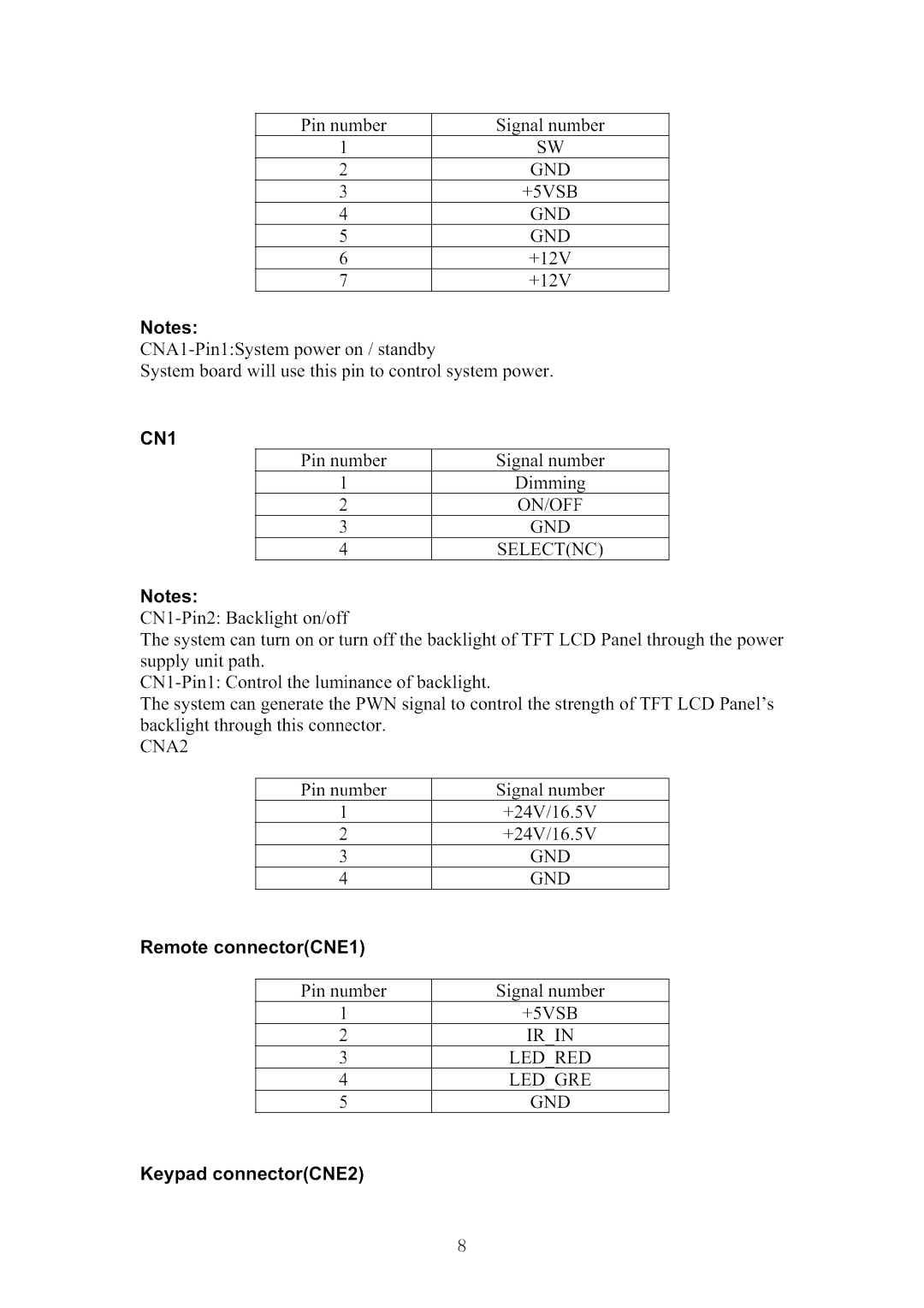
Contents
Main
MSERVICE MANUAL
COLOR TV
Customer Model: HL42XR1 Service Model: HL42XR1a
CHASSIS: MTK5380L
WARNING
CONTENTS
4. Disassemble and
assemble .............................................12
Installation Instructions
6. Operation Instructions ...................................................... 23
Page
1. General Information
1-1 General Guidelines
1-2 Important notice
1-3. How to read this Service Manual
2. Specification
3. LOCATION OF CONTROLS AND COMPONENTS
Page
Page
Page
Page
3-4. LCD Panel
3-4-1 Function Description: Display the signal. 3-4-2 Connector definition
Page
Page
4-5 Remove the power module 4-8 Remove the keypad control
4-6 Remove the Main board
4-7 Remove the remote control
5.installationinstruction
Externa| Equipment Connections
-p-p
'v.--qF_ 88
5.1 External Equipment Connections
Choose Your Connection
0@
"@',o
@@ @@
n []
External A/V Source Setup
Connecting a DVD player
#
Connecting a DTV(digitai TV)
Digital Set=top Box
Connecting a digital audio output
@
@@
5.2 HDNll and DVI Connection
2O
Cable sample
Connecting Headphones
Power source
6. Operation Instructions
Basal information
HL26K1/HL32K1/HL32XK1/HL42XK1
i iili....................
i o
@
o@ @ oo o
@
6-3 Setting Up Your Remote Control
@--
Function introduction
@
--@
7. Electrical parts
7-1. Block diagram
7-2. Circuit Diagram 26
MT8292
L
o
T
....../ f.....4 d.........
_oo_o
I,. 5 ouTI.... t __
,O--OA .....
C0402/SMD 0.8 X(1+1_2K) = 1.2V
I i!,
A 1 1 1_,_o,o_o,1
1f__000_,_yO2200F10V_,000F10V,O_._oF _%.10F
T tq ,ov)
1,9,15+12v <<>> 14+9v _
,N_OUT_ A
9v I I 033sMDrER
! 1
/
/
J
<<>>
POWER DOWN RESET# CIRCUIT DV33
.............
.............T .T Tc'.T' .....
.... ....>./
J_ J_
F_
TS F2,s DT. oF,S T. oF/SMDT oF,SoT oF,SoT oF,So o ;o IvD
o Ly88.3v7_oFTloF-- oF-- oFTloF o.1oF O0 0 ,SMO'
DDR#1
?
ToH402,sMTo0402,s_To0402,s_To0402,s_080_,s_o
* 2_
U
ICE mode O O i
t
10_4 iD4_It_81 t_82 t_83 t_84 t_88 1_8_ t_80 t_88 1_8_
//lf......
R212G ____ _
,_1_-_-
AV33_OM_ _
VERTICAL MOUNT
............. ll
LVDS OUT
........ 1
...... TT
'_4....
.....D12:I.........
_,....Ii@4
il.... :_...............il....
II ................ II ..........
DI:III:......
soG
vo so oporto1 104 04t EEP OM24002L
] r ] r
d vBs3I
s_o GND_UNEm m_ GNOTUNEm ql_l GNO TUNER
............................A..... .......
T.........T....
T ........._ ....
T ........._-....
...... II ............
T lF elco17o
ADCOUTR 7 HPOL n HPGND a
& //// / .... ...v ..........
=
..... II.........A......
TO:AMP
....._UT...._i A_OUT.... . _A_. <<>> _AR.
All capacitor must be >=35V
7-3 .Wiring Connection Diagram
Pov,,,,pp modoi
J
J
Wr k .;_i \._ <i
8. Measurements and Adjustments
Page
Page
Page
Page
Page
Remark: Thedate ofthe chart onlyis a example,pleasedon'tadjustthe factorymodebase onit.
9. Trouble shooting
9-1. Simple check
Horiaontal/vertical pictureshaking Televisionoutof control
I
bars
]i check. ,47
I
I]
_ J Y
]
I
State= No picture
I
9-4. Pannel failure
TCP
(C)
Panel or Polarizer
Bladder between Polarizer and top glass Tine or rigidity arose
!