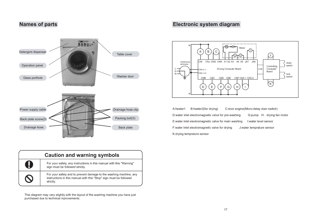
Names of parts
Detergent dispenser
Operation panel
Glass porthole
Power supply cable
Back plate screw(3)
Drainage hose
Table cover
Washer door
Drainage hose clip
Packing bolt(3)
Back plate
Electronic system diagram
N |
|
|
|
|
| Motor |
|
| |
|
|
|
|
|
|
|
| ||
| A |
| B | C |
|
|
| J |
|
|
|
|
|
|
|
|
|
| |
interference | CNI | CNJ CNG CNH | A1 A2 A3 | A4 A5 | JA8 |
| close | ||
eliminator |
|
|
|
|
|
|
|
| |
|
|
|
|
|
|
| Controlling | switch | |
|
|
|
|
|
|
|
| ||
L |
| Driving Computer Board | Line | Computer |
| ||||
G |
|
|
|
|
| Board |
| ||
N |
|
|
|
|
|
| lock | ||
| CNB | CNC | CND | CNE | CNF |
| switch | ||
|
|
| |||||||
| D |
| E | F | G | H | I | K |
|
|
|
|
| ||||||
N |
|
|
|
|
|
|
|
|
|
A:heater1 | B:heater2(for drying) | C:door | ||
D:water inlet electromagnetic valve for | G:pump H drying fan motor | |||
E:water inlet electromagnetic valve for main washing | I:water level sensor | |||
F:water inlet electromagnetic valve for drying | J:water temprature sensor | |||
K:drying temprature sensor |
|
|
| |
Caution and warning symbols
For your safety, any instructions in this manual with this "Warning" sign must be followed strictly.
For your safety and to prevent damage to the washing machine, any instructions in this manual with this "Stop" sign must be followed strictly.
This diagram may vary slightly with the layout of the washing machine you have just purchased due to technical inprovements.
17
