ASSEMBLY
NOTE: Use Teflon® Pipe Tape on all threaded joints. Make sure all joints are securely tighten.
Intake Manifold | Pressure | Intake |
| ||
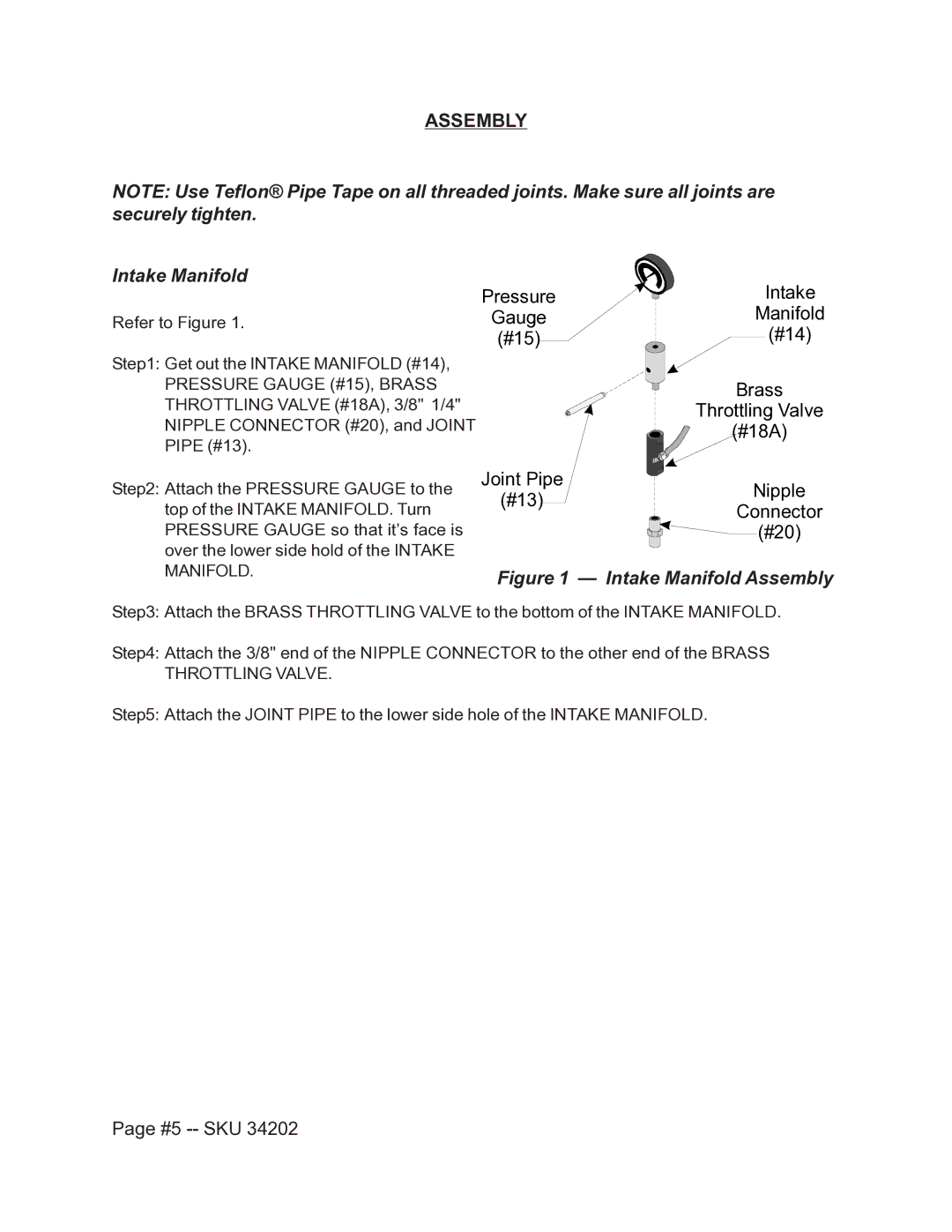
Refer to Figure 1. | Gauge | Manifold |
| (#15) | (#14) |
Step1: Get out the INTAKE MANIFOLD (#14), PRESSURE GAUGE (#15), BRASS THROTTLING VALVE (#18A), 3/8" 1/4" NIPPLE CONNECTOR (#20), and JOINT PIPE (#13).
Step2: Attach the PRESSURE GAUGE to the top of the INTAKE MANIFOLD. Turn PRESSURE GAUGE so that it’s face is over the lower side hold of the INTAKE MANIFOLD.
Brass
Throttling Valve
(#18A)
Joint Pipe
(#13)Nipple
Connector
![]()
![]()
![]() (#20)
(#20)
Figure 1 — Intake Manifold Assembly
Step3: Attach the BRASS THROTTLING VALVE to the bottom of the INTAKE MANIFOLD.
Step4: Attach the 3/8" end of the NIPPLE CONNECTOR to the other end of the BRASS THROTTLING VALVE.
Step5: Attach the JOINT PIPE to the lower side hole of the INTAKE MANIFOLD.
