Handle Bars
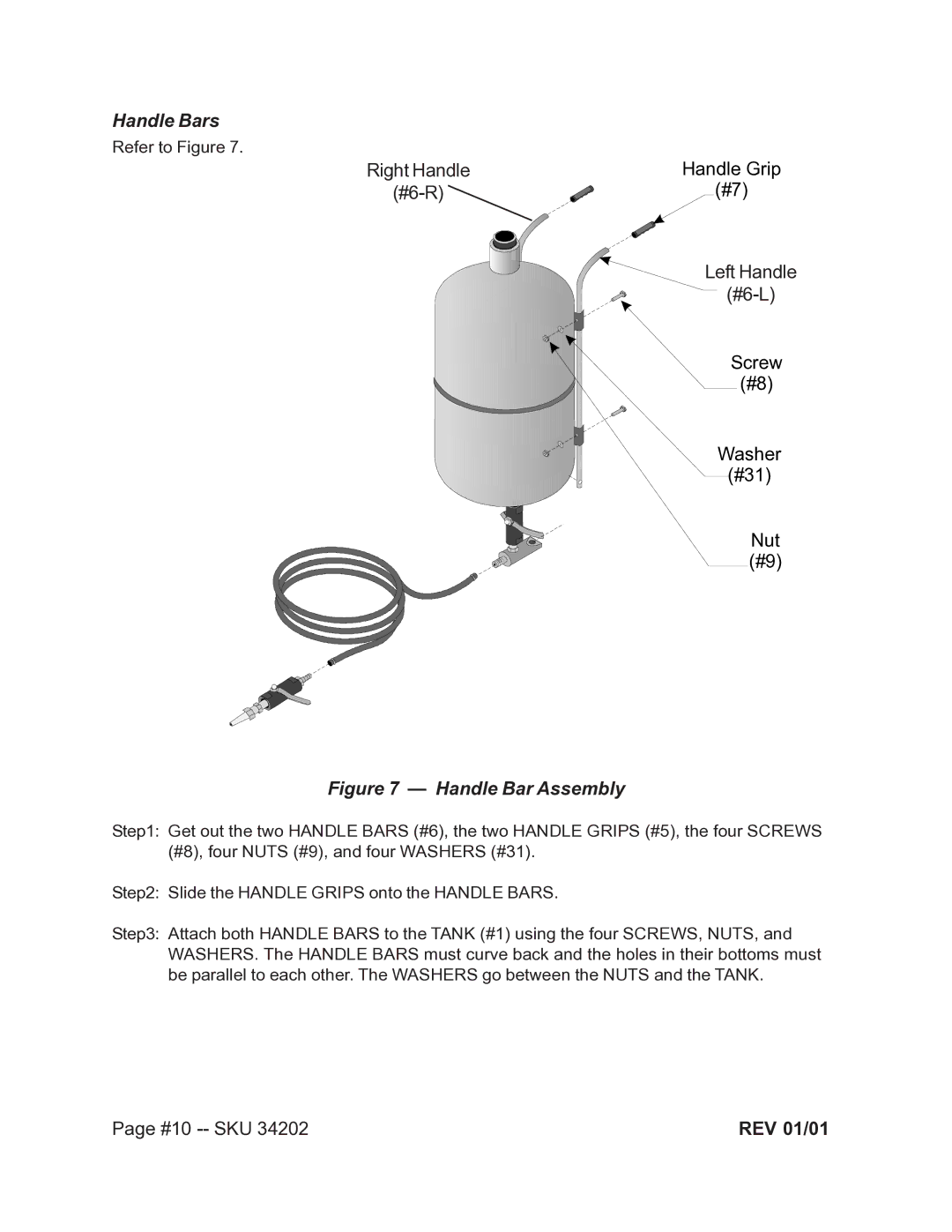
Refer to Figure 7.
Right Handle | Handle Grip |
| (#7) |
Handle Bar
Left Handle
(#6) (#6-L)
Screw
(#8)
Washer
(#31)
Nut (#9)
Figure 7 — Handle Bar Assembly
Step1: Get out the two HANDLE BARS (#6), the two HANDLE GRIPS (#5), the four SCREWS (#8), four NUTS (#9), and four WASHERS (#31).
Step2: Slide the HANDLE GRIPS onto the HANDLE BARS.
Step3: Attach both HANDLE BARS to the TANK (#1) using the four SCREWS, NUTS, and WASHERS. The HANDLE BARS must curve back and the holes in their bottoms must be parallel to each other. The WASHERS go between the NUTS and the TANK.
Page #10 | REV 01/01 |
