STEP 2 (See Diagram 2)
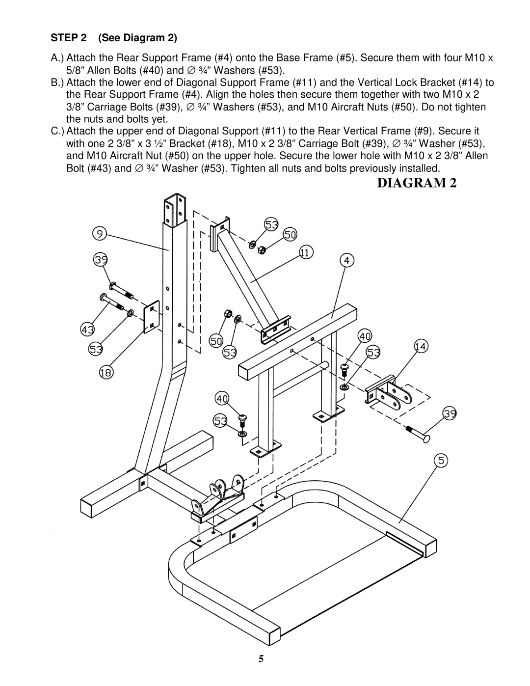
A.) Attach the Rear Support Frame (#4) onto the Base Frame (#5). Secure them with four M10 x 5/8” Allen Bolts (#40) and ∅ ¾” Washers (#53).
B.) Attach the lower end of Diagonal Support Frame (#11) and the Vertical Lock Bracket (#14) to
the Rear Support Frame (#4). Align the holes then secure them together with two M10 x 2 3/8” Carriage Bolts (#39), ∅ ¾” Washers (#53), and M10 Aircraft Nuts (#50). Do not tighten the nuts and bolts yet.
C.) Attach the upper end of Diagonal Support (#11) to the Rear Vertical Frame (#9). Secure it with one 2 3/8” x 3 ½” Bracket (#18), M10 x 2 3/8” Carriage Bolt (#39), ∅ ¾” Washer (#53), and M10 Aircraft Nut (#50) on the upper hole. Secure the lower hole with M10 x 2 3/8” Allen Bolt (#43) and ∅ ¾” Washer (#53). Tighten all nuts and bolts previously installed.
DIAGRAM 2
5