STEP 3 (See Diagram 3)
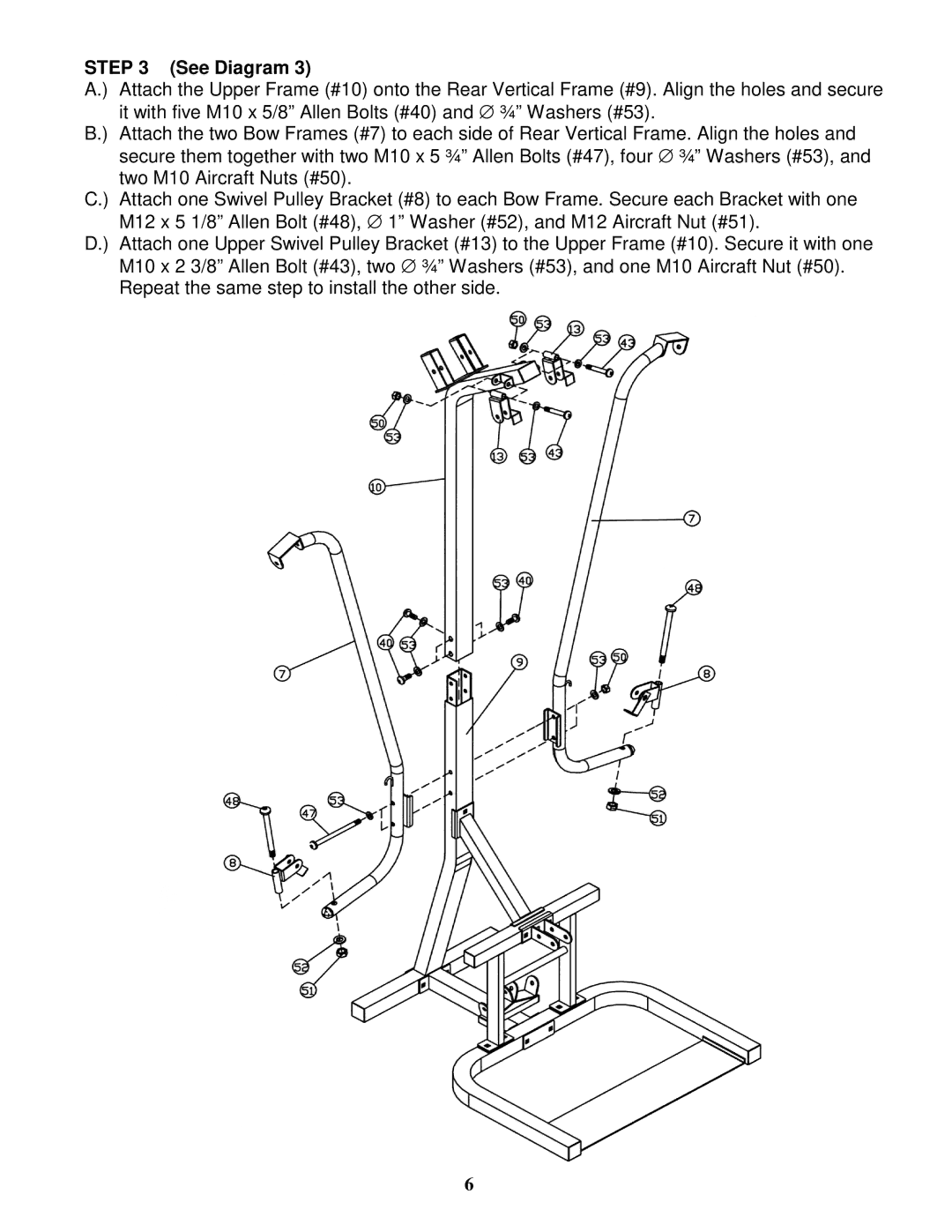
A.) | Attach the Upper Frame (#10) onto the Rear Vertical Frame (#9). Align the holes and secure |
| it with five M10 x 5/8” Allen Bolts (#40) and ∅ ¾” Washers (#53). |
B.) | Attach the two Bow Frames (#7) to each side of Rear Vertical Frame. Align the holes and |
| secure them together with two M10 x 5 ¾” Allen Bolts (#47), four ∅ ¾” Washers (#53), and |
| two M10 Aircraft Nuts (#50). |
C.) Attach one Swivel Pulley Bracket (#8) to each Bow Frame. Secure each Bracket with one M12 x 5 1/8” Allen Bolt (#48), ∅ 1” Washer (#52), and M12 Aircraft Nut (#51).
D.) Attach one Upper Swivel Pulley Bracket (#13) to the Upper Frame (#10). Secure it with one M10 x 2 3/8” Allen Bolt (#43), two ∅ ¾” Washers (#53), and one M10 Aircraft Nut (#50). Repeat the same step to install the other side.
6