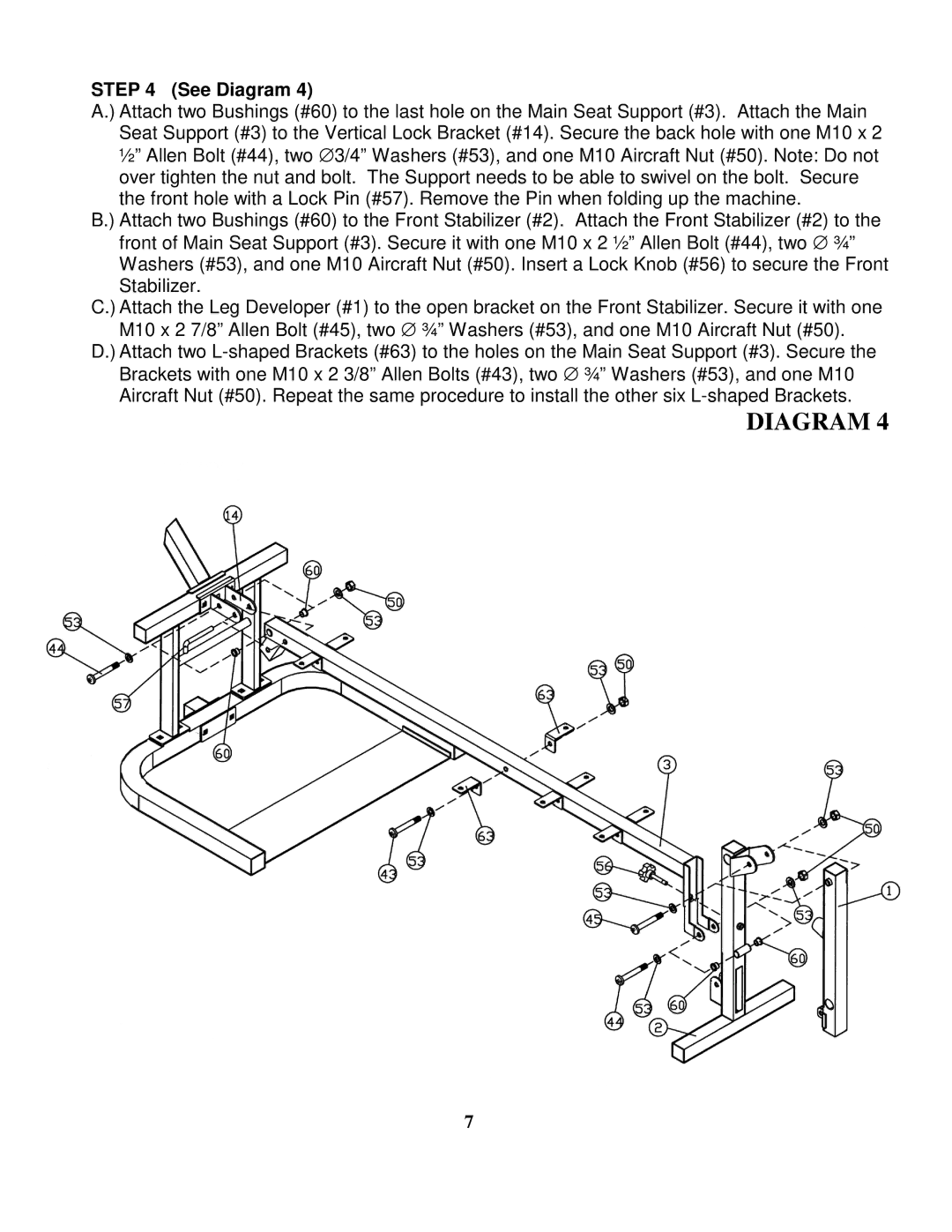
STEP 4 (See Diagram 4)
A.) Attach two Bushings (#60) to the last hole on the Main Seat Support (#3). Attach the Main Seat Support (#3) to the Vertical Lock Bracket (#14). Secure the back hole with one M10 x 2 ½” Allen Bolt (#44), two ∅ 3/4” Washers (#53), and one M10 Aircraft Nut (#50). Note: Do not over tighten the nut and bolt. The Support needs to be able to swivel on the bolt. Secure the front hole with a Lock Pin (#57). Remove the Pin when folding up the machine.
B.) Attach two Bushings (#60) to the Front Stabilizer (#2). Attach the Front Stabilizer (#2) to the front of Main Seat Support (#3). Secure it with one M10 x 2 ½” Allen Bolt (#44), two ∅ ¾” Washers (#53), and one M10 Aircraft Nut (#50). Insert a Lock Knob (#56) to secure the Front Stabilizer.
C.) Attach the Leg Developer (#1) to the open bracket on the Front Stabilizer. Secure it with one M10 x 2 7/8” Allen Bolt (#45), two ∅ ¾” Washers (#53), and one M10 Aircraft Nut (#50).
D.) Attach two
DIAGRAM 4
7