OPERATION
Adjusting the Handle Assembly
1.Determine if you will need a moderate or large amount of leverage for the job.
![]() Lock Pin (#11)
Lock Pin (#11)
Shaft (#15)
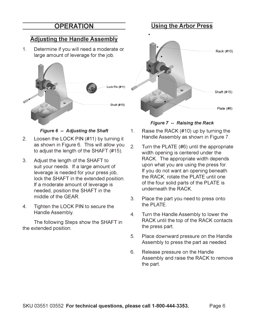
Figure 6 -- Adjusting the Shaft
2.Loosen the LOCK PIN (#11) by turning it as shown in Figure 6. This will allow you to adjust the length of the SHAFT (#15).
3.Adjust the length of the SHAFT to suit your needs. If a large amount of leverage is needed for your press job, lock the SHAFT in the extended position. If a moderate amount of leverage is needed, position the SHAFT in the middle of the GEAR.
4.Tighten the LOCK PIN to secure the Handle Assembly.
The following Steps show the SHAFT in the extended position.
Using the Arbor Press
![]()
![]()
![]() Rack (#10)
Rack (#10)
Shaft (#15)
![]() Plate (#6)
Plate (#6)
Figure 7 -- Raising the Rack
1.Raise the RACK (#10) up by turning the Handle Assembly as shown in Figure 7.
2.Turn the PLATE (#6) until the appropriate width opening is centered under the RACK. The appropriate width depends upon what you are using the press for.
If you do not want an opening beneath the RACK, rotate the PLATE until one of the four solid parts of the PLATE is underneath the RACK.
3.Place the part you need to press onto the PLATE.
4.Turn the Handle Assembly to lower the RACK until the top of the RACK contacts the press part.
5.Place downward pressure on the Handle Assembly to press the part as needed.
6.Release pressure on the Handle Assembly and raise the RACK to remove the part.
SKU 03551 03552 For technical questions, please call | Page 6 |
