|
| CLIP SCREW | CLIP SCREW | |||||||
(#25) | (#25) |
|
|
|
|
| ||||
|
|
|
|
|
|
|
|
| LOCATION | |
|
|
|
|
|
|
|
|
| ||
|
|
|
|
|
|
|
|
| ||
|
|
|
|
|
|
|
|
| BOARD (#23) | |
|
|
|
|
|
|
|
|
| ||
|
|
|
|
|
|
|
|
| BASE (#12) | |
1/2” |
|
|
|
|
|
| 1/2” | |||
|
|
|
|
|
| MOUNTING | ||||
MOUNTING |
|
|
|
|
|
|
|
|
| |
|
|
|
|
|
|
|
|
| ||
|
|
|
|
|
|
|
|
| ||
|
|
|
|
|
|
|
| HOLE | ||
HOLE |
|
|
|
|
|
| ||||
|
|
|
|
|
|
| ||||
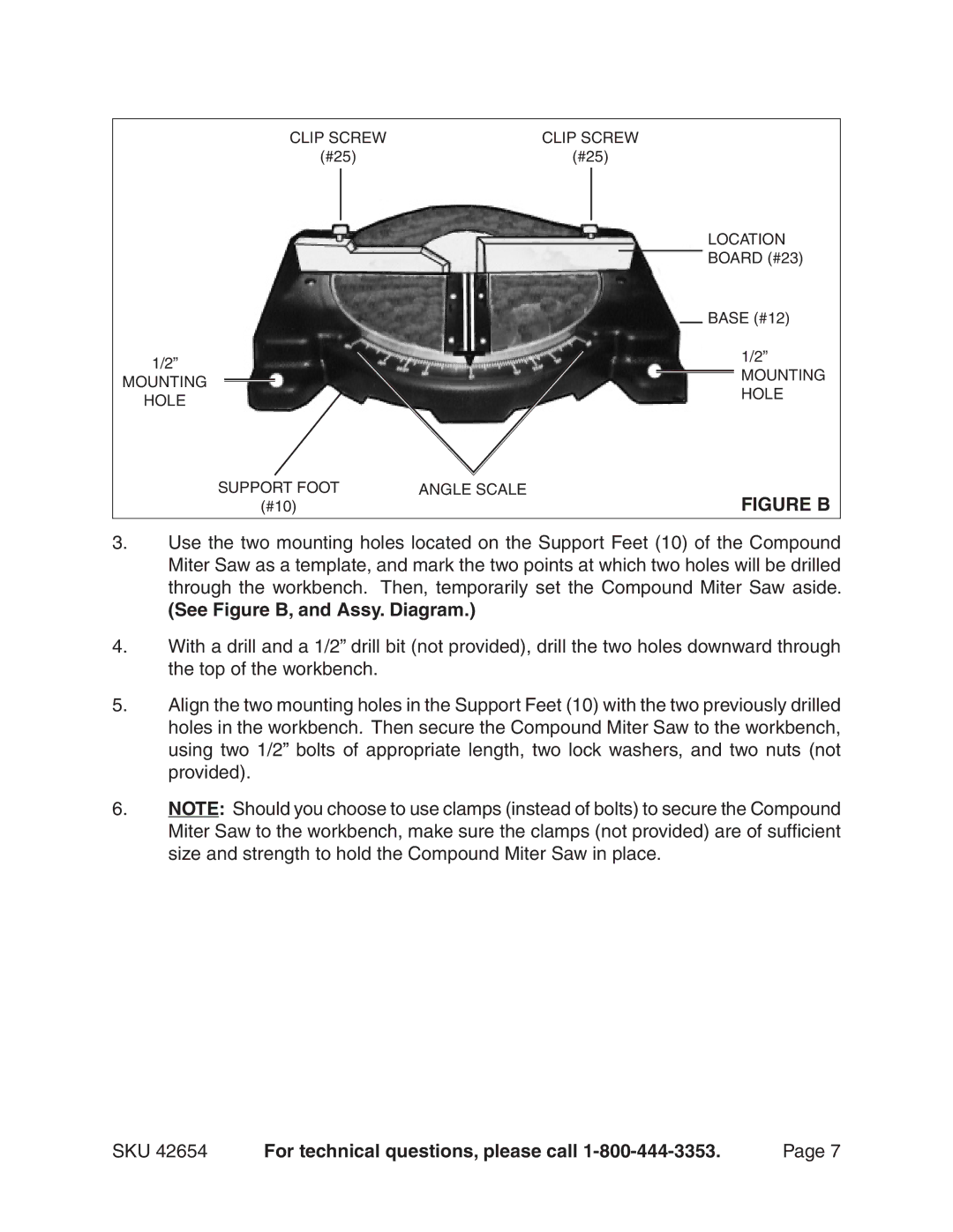
SUPPORT FOOT | ANGLE SCALE | FIGURE B |
(#10) |
|
3.Use the two mounting holes located on the Support Feet (10) of the Compound Miter Saw as a template, and mark the two points at which two holes will be drilled through the workbench. Then, temporarily set the Compound Miter Saw aside.
(See Figure B, and Assy. Diagram.)
4.With a drill and a 1/2” drill bit (not provided), drill the two holes downward through the top of the workbench.
5.Align the two mounting holes in the Support Feet (10) with the two previously drilled holes in the workbench. Then secure the Compound Miter Saw to the workbench, using two 1/2” bolts of appropriate length, two lock washers, and two nuts (not provided).
6.NOTE: Should you choose to use clamps (instead of bolts) to secure the Compound Miter Saw to the workbench, make sure the clamps (not provided) are of sufficient size and strength to hold the Compound Miter Saw in place.
SKU 42654 | For technical questions, please call | Page |