manual including all text under subheadings therein before set up or use of this product.
To prevent serious injury
from accidental operation:
Turn off and disable the motor before assembling or making any adjustments to the compressor pump.
To prevent serious injury
and death from improper installation:
ONLY a qualified engineer with appropriate certifications may attempt designing a new compressor to ensure that all required safety and control elements are in place and will work together properly and safely. This compressor pump is intended ONLY as a replacement for a similarly rated pump on an existing compressor that includes all other needed components. Constructing a new compressor using this pump is not covered by this manual.
Note: For additional information regarding the parts listed in the following pages, refer to the Assembly Diagram near the end of this manual.
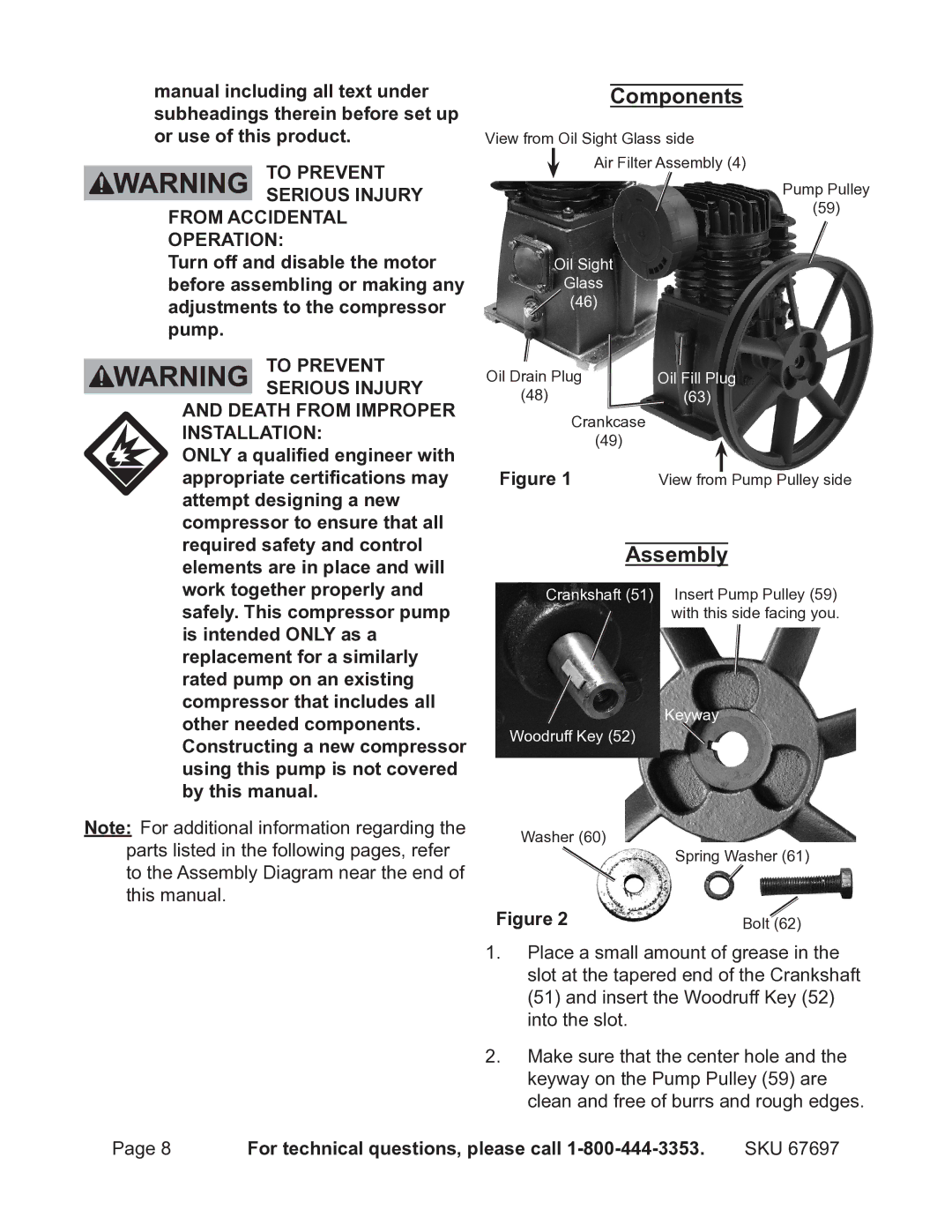
Components
View from Oil Sight Glass side
Air Filter Assembly (4)
Pump Pulley
(59)
Oil Sight
Glass
![]() (46)
(46)
Oil Drain Plug | Oil Fill Plug | ||
(48) | (63) |
|
|
Crankcase |
|
|
|
(49) |
|
|
|
Figure 1 | View from |
| Pump Pulley side |
| |||
Assembly
Crankshaft (51) Insert Pump Pulley (59) with this side facing you.
Keyway
Woodruff Key (52)
Washer (60)
Spring Washer (61)
Figure 2 | Bolt (62) |
1.Place a small amount of grease in the slot at the tapered end of the Crankshaft (51) and insert the Woodruff Key (52) into the slot.
2.Make sure that the center hole and the keyway on the Pump Pulley (59) are clean and free of burrs and rough edges.
Page 8 | For technical questions, please call | SKU 67697 |
