![]() WARNING! If either power cord or plug is damaged, do not use the pump. The power cord or plug
WARNING! If either power cord or plug is damaged, do not use the pump. The power cord or plug
may only be repaired by a certified electrician.
Areas of use
1.This pump is designed to pump clear water only.
2.This pump is designed for use as a basement pump. When installed in a shaft, this pump provides some protection from basement flooding.
3.This pump can also be used to transfer water (e.g. household, farming, plumbing).
3.Fit a sump cover with a hole for the output pipe and power cords. Thread the Power Cords through their holes, but do not plug them in yet. Set the sump cover aside for now.
Note: The sump cover can also be fitted with a vent pipe, if desired.
4. Attach a discharge pipe to the Pump Outlet.
Note: Wrap all threaded connections with PTFE thread seal tape.
To discharge | |
(away from foundation) | Receptacle |
Installation Instructions
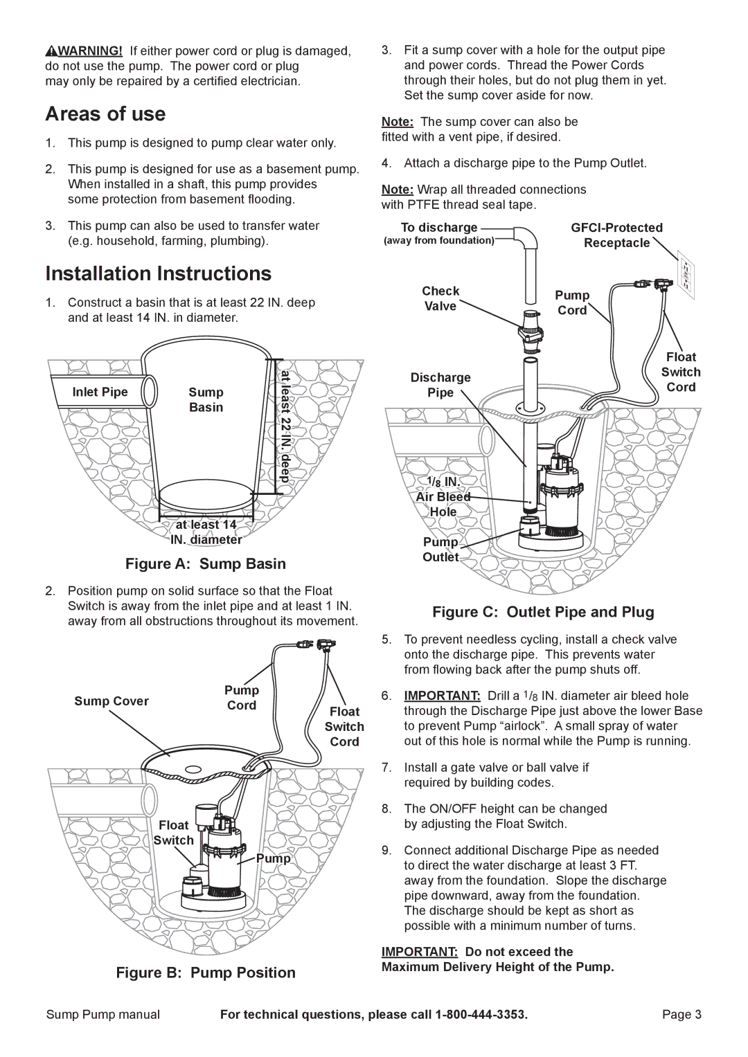
1.Construct a basin that is at least 22 IN. deep and at least 14 IN. in diameter.
|
| at |
Inlet Pipe | Sump | least |
| Basin | |
|
| 22 IN. deep |
at least 14
IN. diameter
Figure A: Sump Basin
2.Position pump on solid surface so that the Float Switch is away from the inlet pipe and at least 1 IN. away from all obstructions throughout its movement.
Pump
Sump CoverCordFloat
Switch
Cord
Float
Switch
![]() Pump
Pump
Figure B: Pump Position
Check | Pump | |
Valve | Cord | |
| Float | |
Discharge | Switch | |
Cord | ||
Pipe | ||
|
1/8 IN.
Air Bleed
Hole
Pump
Outlet
Figure C: Outlet Pipe and Plug
5.To prevent needless cycling, install a check valve onto the discharge pipe. This prevents water from flowing back after the pump shuts off.
6.IMPORTANT: Drill a 1/8 IN. diameter air bleed hole through the Discharge Pipe just above the lower Base to prevent Pump “airlock”. A small spray of water out of this hole is normal while the Pump is running.
7.Install a gate valve or ball valve if required by building codes.
8.The ON/OFF height can be changed by adjusting the Float Switch.
9.Connect additional Discharge Pipe as needed to direct the water discharge at least 3 FT. away from the foundation. Slope the discharge pipe downward, away from the foundation. The discharge should be kept as short as possible with a minimum number of turns.
IMPORTANT: Do not exceed the
Maximum Delivery Height of the Pump.
Sump Pump manual | For technical questions, please call | Page 3 |