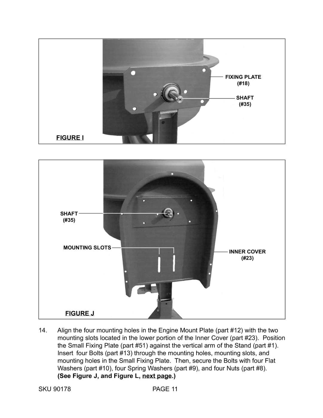
FIXING PLATE
(#18)
SHAFT
(#35)
FIGURE I
SHAFT
(#35)
MOUNTING SLOTS
INNER COVER
(#23)
FIGURE J
14.Align the four mounting holes in the Engine Mount Plate (part #12) with the two mounting slots located in the lower portion of the Inner Cover (part #23). Position the Small Fixing Plate (part #51) against the vertical arm of the Stand (part #1). Insert four Bolts (part #13) through the mounting holes, mounting slots, and mounting holes in the Small Fixing Plate. Then, secure the Bolts with four Flat Washers (part #10), four Spring Washers (part #9), and four Nuts (part #8).
(See Figure J, and Figure L, next page.)
SKU 90178 | PAGE 11 |