ASSEMBLY INSTRUCTIONS
NOTE: For additional information regarding the parts listed in the following pages, refer to the Assembly Diagram on the last page.
The power to the outlet box must be disconnected before attempting to install this item.
If the power is left connected during installation, or if the power comes on accidentally, SEVERE PERSONAL INJURY or DEATH can occur.
1.BEFORE STARTING THE INSTALLA- TION MAKE CERTAIN THAT:
A.All needed tools and materials are present at the work area. Weather- proof sealant is not included.
B.Sufficient time is allotted for complet- ing the installation.
C.It is a dry day with no chance of rain.
Leaving the work area without finishing the installation creates a dangerous situ- ation, and should be avoided at all costs.
2.This device is installed on an electri- cal circuit that has sufficient voltage to SERIOUSLY INJURE or KILL you. If any doubt exists about your capa- bility to install this unit safely and properly, this unit should be installed by a licensed electrician.
3.Select an appropriate
A.Should be unblocked for optimal illu- mination and sensor range.
B.Must not block or interfere with any walkways.
C.Must be out of children’s reach.
4.Disconnect all power connected to the outlet box that this item is to be
installed on. Visibly label the power switch leading to the circuit, “Work in progress on this circuit, DO NOT TURN POWER ON.”
5.Remove the cover from the outlet box. Use a multimeter, set to a setting appro- priate for testing 120 VAC, to determine that the power to the outlet is truly dis- connected.
6.Parts
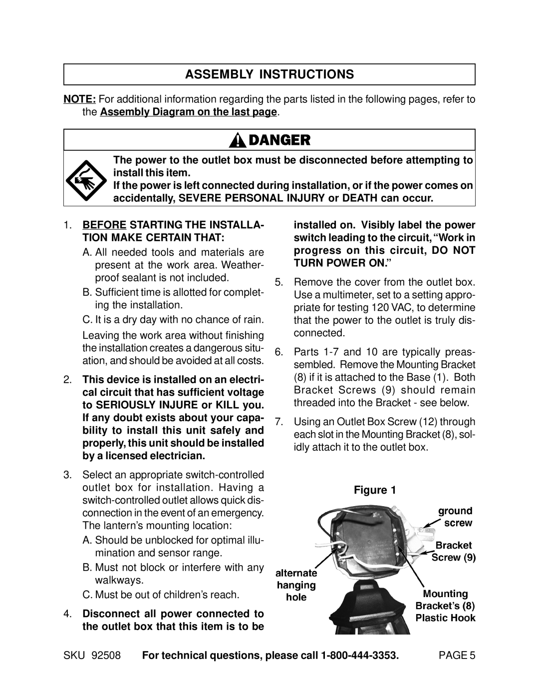
(8)if it is attached to the Base (1). Both Bracket Screws (9) should remain threaded into the Bracket - see below.
7.Using an Outlet Box Screw (12) through each slot in the Mounting Bracket (8), sol- idly attach it to the outlet box.
Figure 1
SKU 92508 For technical questions, please call | PAGE 5 |
