SYMBOLOGY
V~
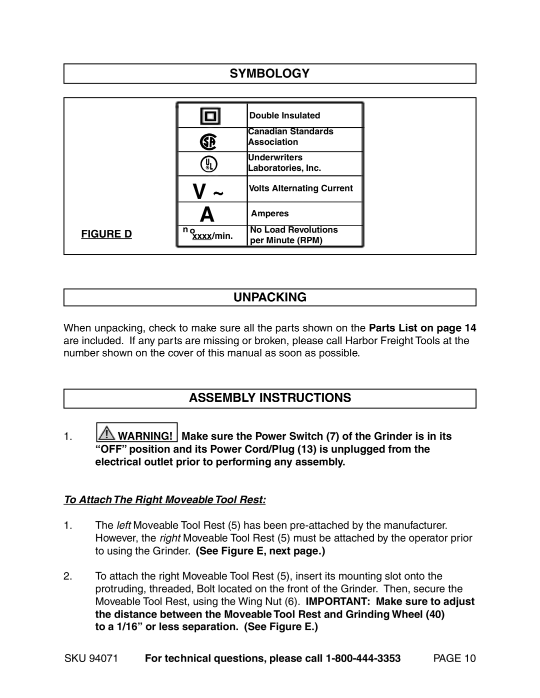
A
Double Insulated
Canadian Standards Association
Underwriters
Laboratories, Inc.
Volts Alternating Current
Amperes
FIGURE D | n o | No Load Revolutions |
xxxx/min. | per Minute (RPM) | |
|
|
UNPACKING
When unpacking, check to make sure all the parts shown on the Parts List on page 14 are included. If any parts are missing or broken, please call Harbor Freight Tools at the number shown on the cover of this manual as soon as possible.
ASSEMBLY INSTRUCTIONS
1.![]()
![]() WARNING! Make sure the Power Switch (7) of the Grinder is in its “OFF” position and its Power Cord/Plug (13) is unplugged from the electrical outlet prior to performing any assembly.
WARNING! Make sure the Power Switch (7) of the Grinder is in its “OFF” position and its Power Cord/Plug (13) is unplugged from the electrical outlet prior to performing any assembly.
To Attach The Right Moveable Tool Rest:
1.The left Moveable Tool Rest (5) has been
2.To attach the right Moveable Tool Rest (5), insert its mounting slot onto the protruding, threaded, Bolt located on the front of the Grinder. Then, secure the Moveable Tool Rest, using the Wing Nut (6). IMPORTANT: Make sure to adjust the distance between the Moveable Tool Rest and Grinding Wheel (40)
to a 1/16” or less separation. (See Figure E.)
SKU 94071 | For technical questions, please call | PAGE 10 |