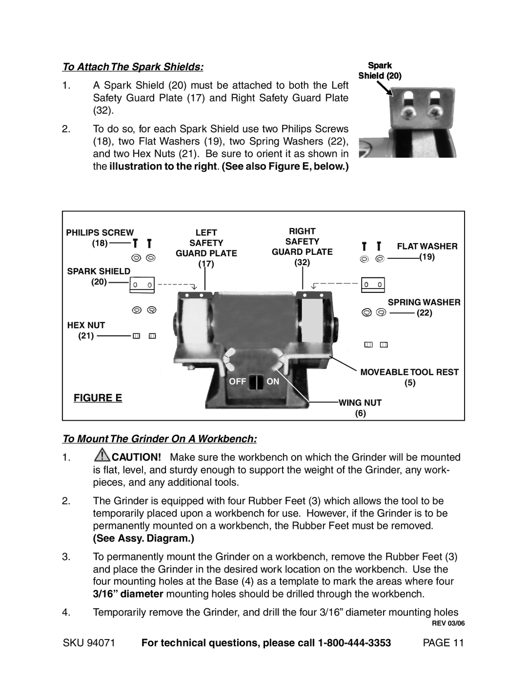
To Attach The Spark Shields:
1.A Spark Shield (20) must be attached to both the Left Safety Guard Plate (17) and Right Safety Guard Plate (32).
2.To do so, for each Spark Shield use two Philips Screws (18), two Flat Washers (19), two Spring Washers (22), and two Hex Nuts (21). Be sure to orient it as shown in the illustration to the right. (See also Figure E, below.)
PHILIPS SCREW | LEFT | RIGHT |
|
|
|
|
| ||||||||
(18) |
|
|
|
| SAFETY | SAFETY |
|
| FLAT WASHER | ||||||
|
|
|
|
| |||||||||||
|
|
|
|
|
| GUARD PLATE | GUARD PLATE |
|
| ||||||
|
|
|
|
|
|
|
|
|
| (19) | |||||
SPARK SHIELD | (17) | (32) |
|
|
|
| |||||||||
|
|
|
|
| |||||||||||
|
|
|
|
|
|
|
|
|
| ||||||
(20) |
|
|
|
|
|
|
|
|
|
| SPRING WASHER | ||||
|
|
|
|
|
|
|
|
|
| ||||||
|
|
|
|
|
|
|
|
|
|
|
| ||||
|
|
|
|
|
|
|
|
|
|
|
| ||||
HEX NUT |
|
|
|
|
|
|
| (22) | |||||||
|
|
|
|
|
| ||||||||||
|
|
|
|
|
|
|
|
|
| ||||||
(21) |
|
|
|
|
|
| OFF | ON | MOVEABLE TOOL REST | ||||||
|
|
|
|
|
| ||||||||||
|
|
|
|
|
|
| |||||||||
|
|
|
|
|
|
| (5) |
| |||||||
FIGURE E |
|
|
|
|
| WING NUT | |||||||||
|
|
|
|
|
|
|
|
|
|
| |||||
|
|
|
|
|
|
|
|
|
|
| (6) |
|
|
|
|
|
|
|
|
|
|
|
|
|
|
|
|
|
|
|
|
To Mount The Grinder On A Workbench:
1.![]() CAUTION! Make sure the workbench on which the Grinder will be mounted is flat, level, and sturdy enough to support the weight of the Grinder, any work- pieces, and any additional tools.
CAUTION! Make sure the workbench on which the Grinder will be mounted is flat, level, and sturdy enough to support the weight of the Grinder, any work- pieces, and any additional tools.
2.The Grinder is equipped with four Rubber Feet (3) which allows the tool to be temporarily placed upon a workbench for use. However, if the Grinder is to be permanently mounted on a workbench, the Rubber Feet must be removed.
(See Assy. Diagram.)
3.To permanently mount the Grinder on a workbench, remove the Rubber Feet (3) and place the Grinder in the desired work location on the workbench. Use the four mounting holes at the Base (4) as a template to mark the areas where four 3/16” diameter mounting holes should be drilled through the workbench.
4.Temporarily remove the Grinder, and drill the four 3/16” diameter mounting holes
REV 03/06
SKU 94071 | For technical questions, please call | PAGE 11 |