Flat Washer (26) and Lock Washer (27). (See Figure 3 & 4)
4.Mount Pivot Indicator (70) to the Bar Holder (74) using the Adjusting Knob
(75) and Flat Washer (26) and finger tighten. (See Figure 3 )
5.Tighten all fasteners. Make sure Pivot Indicator operates smoothly when Angle Adjustment Knob (75) is loosened.
Figure 5
Bar Holder (74)
Support Shaft (76) flat side
6.Slide Support Shaft (76) into Bar
Holder (74) aligning flat face of the shaft with set screws and tighten securely. Slide Support Shaft
(76) into existing hole on side of Machine Body (33) and with wrench (not supplied), tighten Bolt (32). (See Figure 5 )
Mounting Table for use as Belt
Sander
NOTE: The Table (69) may be used for both horizontal and vertical operations.
1.Remove Table from Machine Body using reverse procedures in number 6 of “Disc Sander” section above.
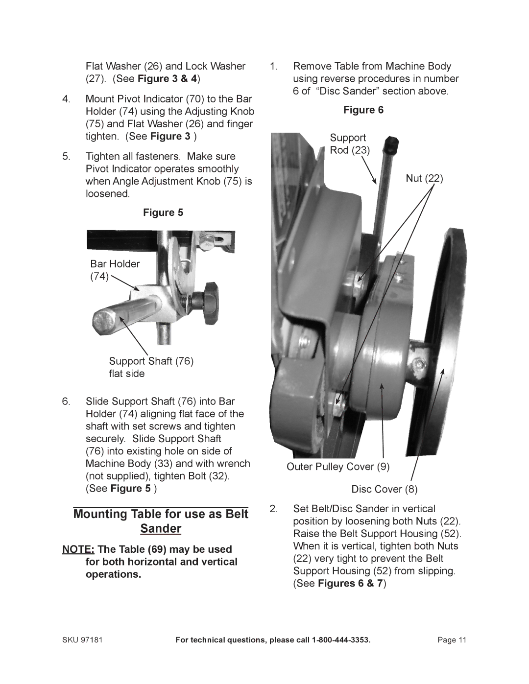
Figure 6
Support
Rod (23)
Nut (22)
Outer Pulley Cover (9)
Disc Cover (8)
2.Set Belt/Disc Sander in vertical position by loosening both Nuts (22). Raise the Belt Support Housing (52). When it is vertical, tighten both Nuts (22) very tight to prevent the Belt Support Housing (52) from slipping. (See Figures 6 & 7)
SKU 97181 | For technical questions, please call | Page 11 |
